Back module for an exoskeleton structure

a back module and exoskeleton technology, applied in the field of back modules for exoskeleton structures, can solve the problems of reducing the mobility of users, exoskeletons that do not allow the back of users to bend, and exoskeletons that do not allow users to move easily in space, so as to reduce the mobility of users

Active Publication Date: 2019-11-14
SAFRAN ELECTRONICS & DEFENSE +1
View PDF3 Cites 11 Cited by
  • Summary
  • Abstract
  • Description
  • Claims
  • Application Information

AI Technical Summary

Benefits of technology

[0009]This aim is achieved within the scope of the present invention thanks to a back module for an exoskeleton structure, comprising a spinal column segment designed to extend along a spinal column of a user, the spinal column segment comprising a plurality of vertebral elements, stacked on one another, and a flexible connecting element connecting the vertebral elements to one another, the spinal column segment having a stable equilibrium position in which the flexible connecting element holds the vertebral elements supported against one another, and the flexible connecting element being elastic so that, during a movement of the back of the user, the flexible connecting element allows a movement of the vertebral elements with respect to one another, while exerting a return force tending to return the spinal column segment to the stable equilibrium position.
[0010]The spinal column segment being formed from a plurality of vertebral elements supported against one another, it allows transmission of a vertical load exerted on the back module and accommodating the movements of the upper body of the user. In fact, the flexible element allows a certain degree of freedom of the vertebral elements with respect to one another, which confers a certain freedom of movement on the spinal column.

Problems solved by technology

These exoskeletons do not allow bending of the back of the user.
These exoskeletons do not allow the user to move easily in space and do not respect his biomechanics.
In other words, in both cases, these exoskeletons have a tendency to reduce the mobility of the user.

Method used


Image

  • Back module for an exoskeleton structure
  • Back module for an exoskeleton structure
  • Back module for an exoskeleton structure

Examples


Embodiment Construction

Modular Structure

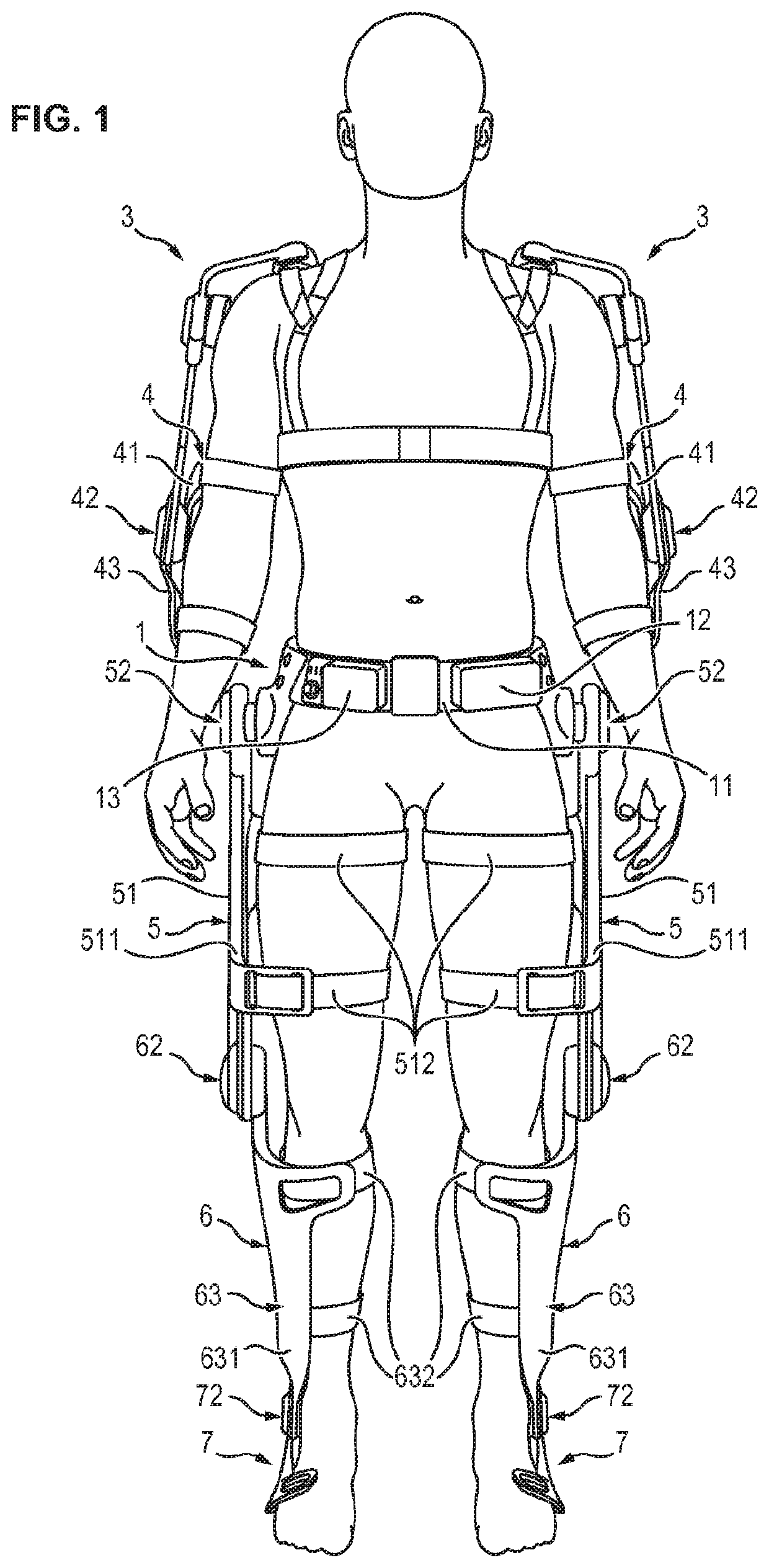
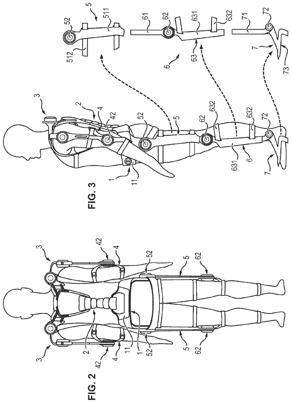
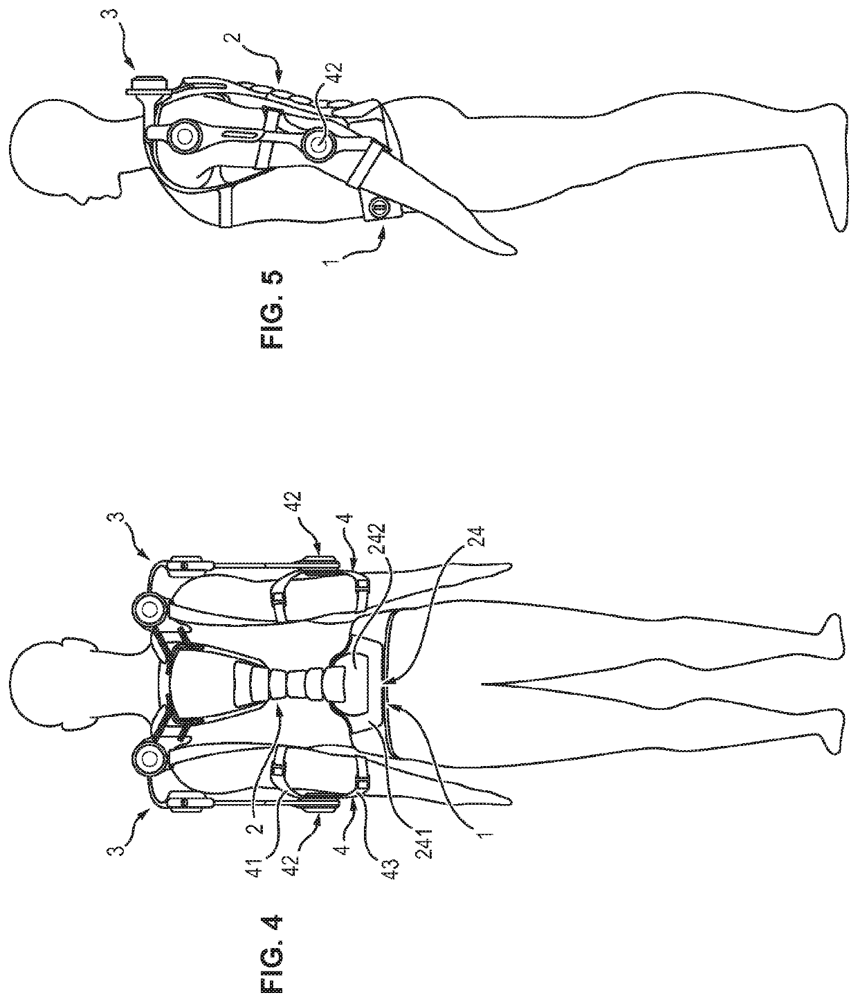
[0042]In FIGS. 1 to 7, the exoskeleton structure shown comprises a base module 1, a back module 2, two shoulder modules 3, two elbow modules 4, two hip modules 5, two knee modules 6, two foot modules 7 and a backpack support module 14.

[0043]The exoskeleton structure illustrated in these figures can be used in different configurations, so as to obtain different exoskeletons adapted to different uses.

[0044]In a first configuration illustrated in FIGS. 1 to 3, the exoskeleton is formed by assembling the base module 1, the back module 2, the two shoulder modules 3, the two elbow modules 4, the two hip modules 5, the two knee modules 6 and the two foot modules 7.

[0045]In a second configuration illustrated in FIGS. 4 and 5, the exoskeleton is formed by assembling only the base module 1, the back module 2, the two shoulder modules 3 and the two elbow modules 4.

[0046]In a third configuration illustrated in FIGS. 6 and 7, the exoskeleton is formed by assembling only the base...


PUM


Abstract

The invention relates to a back module (2) for an exoskeleton structure, comprising a spinal column segment (21) designed to extend along a spinal column of a user, the spinal column segment (21) comprising a plurality of vertebral elements (211), stacked on one another, and a flexible connecting element (212) connecting the vertebral elements (211) to one another, the spinal column segment (21) having a stable equilibrium position in which the flexible connecting element (212) holds the vertebral elements (211) supported against one another, and the flexible connecting element (212) being elastic so that, during a movement of the back of the user, the flexible connecting element (212) allows a movement of the vertebral elements (211) with respect to one another, while exerting a return force tending to return the spinal column segment (21) the stable equilibrium position.

Description

FIELD OF THE INVENTION[0001]The invention relates to a back module for an exoskeleton structure that provides force assistance to a user.PRIOR ART[0002]Exoskeletons that provide force assistance are mechanical structures which duplicate the structure of the human skeleton and which allow an improvement in the physical capacities of the human body.[0003]There exist different types of exoskeletons that provide force assistance, which depend on the tasks to be accomplished by the user.[0004]Known in particular are exoskeletons for the upper body allowing the upper members to be relieved during the transportation of heavy loads and / or during repeated movement. These exoskeletons allow a limitation of the risks of muscular-skeletal disorders.[0005]These exoskeletons, however, generally have a non-articulated architecture at the back, with single point of mobility at the hip joint. These exoskeletons do not allow bending of the back of the user.[0006]In other exoskeletons, the mass lifted...

Claims


Application Information

Patent Timeline
Patent Type & Authority Applications(United States)
IPC IPC(8): B25J9/00A61H3/00
CPCA61H2205/081A61H2201/1215A61H2201/1626A61H2201/1616A61H2201/1638A61H2201/165B25J9/0006A61H2201/5007A61H2201/1642A61H2003/007A61H3/00B25J9/08B25J19/0025
Inventor GRENIER, JORDANEBAPTISTA, JONATHANTHIEFFRY, ROLANDVAURE, ALEXANDRE
Owner SAFRAN ELECTRONICS & DEFENSE
Why Eureka
Try Eureka