Connector unit with terminal block

Active Publication Date: 2019-11-14
YAZAKI CORP
View PDF18 Cites 6 Cited by
  • Summary
  • Abstract
  • Description
  • Claims
  • Application Information

AI Technical Summary

Benefits of technology

The patent text talks about a new way to connect terminals to a circuit board that eliminates the need for screws and reduces the cost associated with it. Instead, a positioning protrusion is inserted into the board to prevent the terminal block from tilting while it is being connected to the board. The technical effect of this new method is reduced component cost, manufacturing process, and manufacturing facility, resulting in lower product costs.

Problems solved by technology

However, the screwing of the terminal block to the board requires costs for screws.
These requirements lead to increase in a component cost, a manufacture process, and a manufacturing facility, and causes product cost increase.
However, when the terminal block is not directly fixed to the board and external force is applied to the board before the terminal is fixed by soldering, the terminal block is potentially inclined so that the terminal is not arranged in an opening of the housing.
In addition, solder potentially solidifies while the terminal block is separated from the board due to the surface tension of solder, which results in insufficient fixation of the terminal block to the board.
Accordingly, the stress applied to the soldering place potentially generates cracks of the solder and causes defect of the state of conduction between the board and the terminal at the soldering place.
The disclosure is directed to a connector unit that can prevent stress from concentrating on a connection place between a terminal of a terminal block and a board without employing a structure in which the terminal block is directly fixed to the board, which leads to increase in a product cost.
Thus, it is possible to achieve a configuration with reduced increase in a component cost, a manufacturing process, and a manufacturing facility, which leads to increase in a product cost of the connector unit.
Accordingly, stress can be prevented from concentrating on the connection place between the terminal of the terminal block and the board without employing a structure in which the terminal block is directly fixed to the board, which leads to increase in a product cost.

Method used


Image

  • Connector unit with terminal block
  • Connector unit with terminal block
  • Connector unit with terminal block

Examples


Embodiment Construction

[0029]In the following detailed description, for purposes of explanation, numerous specific details are set forth in order to provide a thorough understanding of the disclosed embodiments. It will be apparent, however, that one or more embodiments may be practiced without these specific details. In other instances, well-known structures and devices are schematically shown in order to simplify the drawing.

[0030]Description will be hereinbelow provided for embodiments of the present invention by referring to the drawings. It should be noted that the same or similar parts and components throughout the drawings will be denoted by the same or similar reference signs, and that descriptions for such parts and components will be omitted or simplified. In addition, it should be noted that the drawings are schematic and therefore different from the actual ones.

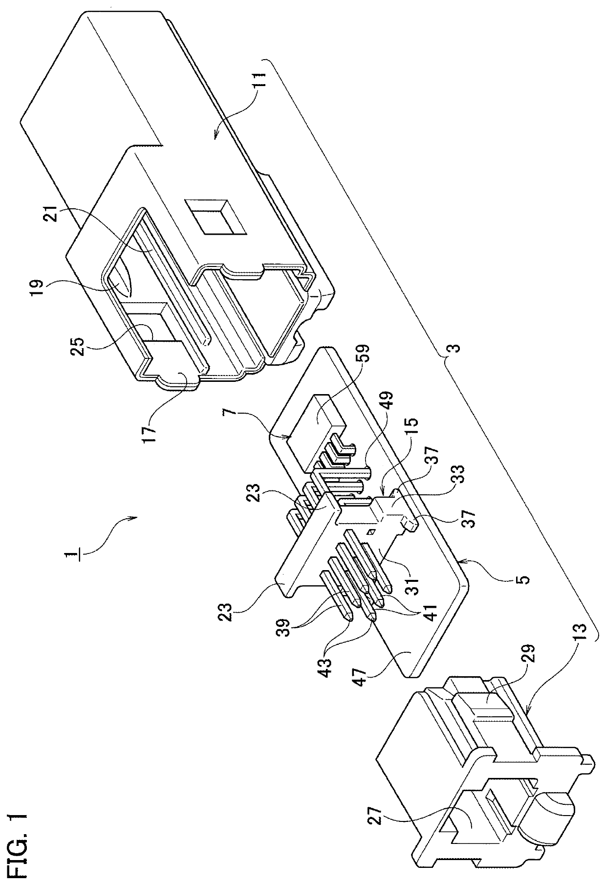
[0031]The following describes an embodiment of the present invention with reference to the accompanying drawings. FIG. 1 is an explode...


PUM


Abstract

A connector unit includes: a housing including a guide rail inside the housing; a terminal block including a flange and configured to hold a terminal having one end exposed in an opening of the housing, the terminal block being housed inside the housing with the flange supported by the guide rail; and a board connected with the other end of the terminal and housed in the housing with the board suspended from the terminal block through the terminal.

Description

CROSS REFERENCE TO RELATED APPLICATION[0001]This application is based upon and claims the benefit of priority from the prior Japanese Patent Application No. 2018-092099, filed on May 11, 2018, the entire contents of which are incorporated herein by reference.BACKGROUND1. Technical Field[0002]The disclosure relates to a connector unit in which a terminal block holding a terminal of a connector is fixed to a board.2. Related Art[0003]Japanese Patent Laid-open No. 2018-33196 discloses a connector unit in which a terminal of a connector is connected with a board. In the connector unit, a terminal block holding the terminal is screwed to the board, the terminal is inserted into a through-hole of the board and soldered, and then the board is housed in a housing. In the connector unit, when the board is housed in the housing, the terminal is arranged in an opening of the housing into which another connector is inserted.SUMMARY[0004]When such a connector unit thus configured is assembled, t...

Claims


Application Information

Patent Timeline
IPC IPC(8): H01R13/502H01R12/58H01R13/41
CPCH01R13/502H01R12/58H01R13/41H01R12/57H01R12/7052H01R12/707H01R12/724H01R13/6658H05K1/182H05K3/3447H05K2201/10189H05K2203/167H05K3/306
Inventor YAMAMOTO, SHOHEI
Owner YAZAKI CORP
Why Eureka
Try Eureka