
Estimation of maximum load amplitudes in drilling systems independent of sensor position

a technology of maximum load and sensor position, applied in the field of subsurface operations, can solve the problems of reducing the quality of measurements, reducing the penetration rate of causing severe vibration in drill strings and bottomhole assemblies

Active Publication Date: 2019-11-28
BAKER HUGHES INC
View PDF0 Cites 7 Cited by
  • Summary
  • Abstract
  • Description
  • Claims
  • Application Information

AI Technical Summary

Benefits of technology

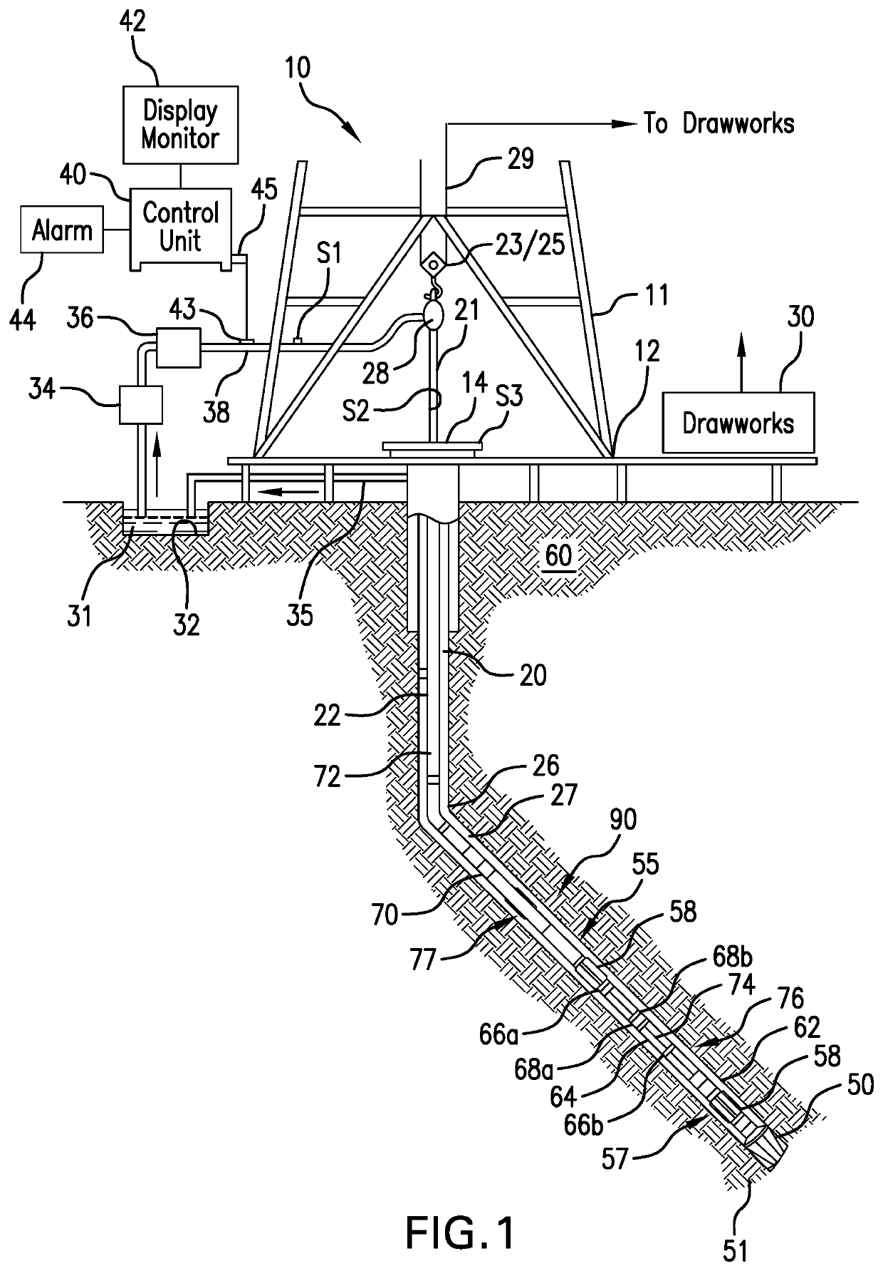
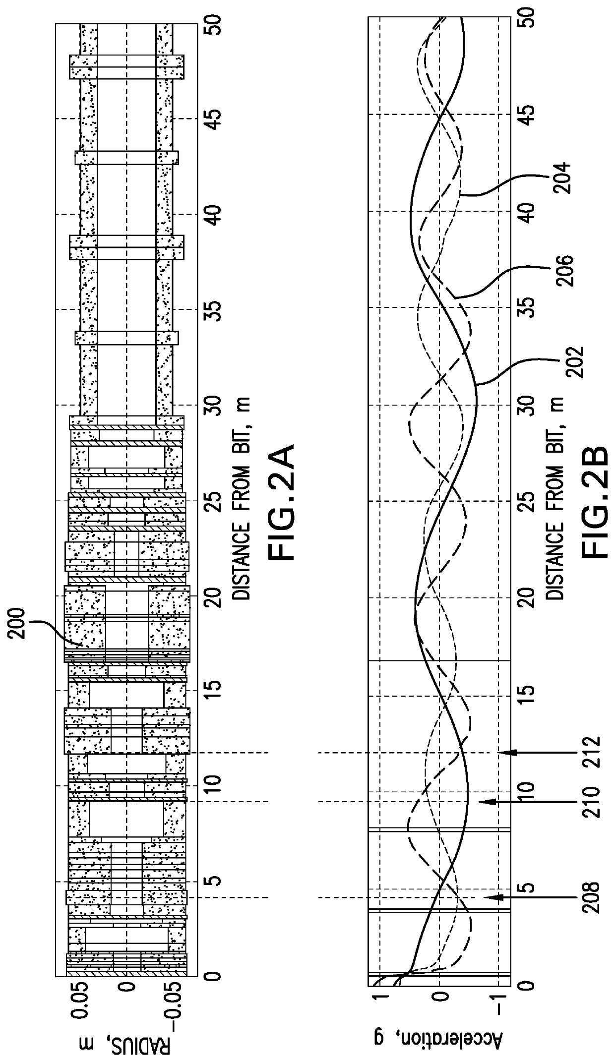
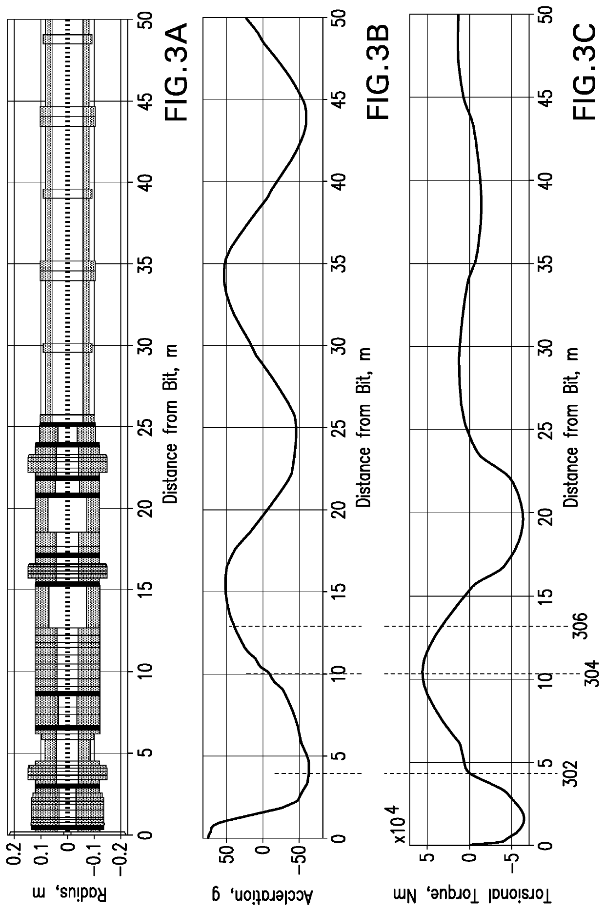
The patent describes systems and methods for reducing vibrations in downhole strings during drilling operations. The systems measure loads during drilling and create data based on the loads and the distance between the measurements. The data is then compared to load limits, and if the data exceeds the limits, a vibration mitigation operation is performed. The technical effects are improved stability and efficiency in drilling operations through reduced vibration.

Problems solved by technology

During drilling operations, severe vibrations in drill strings and bottomhole assemblies can be caused by cutting forces at the bit or mass imbalances in downhole tools such as mud motors.
Such vibrations can result in reduced rates of penetration, reduced quality of measurements, and, potentially, downhole failures.
However, the interpretation of this data is limited due to several reasons.
Moreover, filter characteristics and sampling rates can limit the frequencies that contribute to the overall vibration amplitude level.
Additionally, as will be appreciated by those of skill in the art, the sensor positions are not perfectly aligned and / or the position tolerances of the sensors may be too high.
Therefore, the separation of lateral, radial, and tangential acceleration (vibration) may not be accurate.

Method used


Image

  • Estimation of maximum load amplitudes in drilling systems independent of sensor position
  • Estimation of maximum load amplitudes in drilling systems independent of sensor position
  • Estimation of maximum load amplitudes in drilling systems independent of sensor position

Examples


embodiment 1

[0109]A method for mitigating vibration in a downhole string, the method comprising: performing a drilling operation using a disintegrating tool on an end of the downhole string; obtaining a first load measurement of a first load during the drilling operation and creating first load measurement data using a first load sensor in the downhole string; obtaining a second load measurement of a second load during the drilling operation and creating second load measurement data using a second load sensor in the downhole string, wherein the second load measurement is different from the first load measurement and the first load sensor and the second load sensor are separated by a sensor distance; determining at least one of (i) a first representative value of the first load along the downhole string from the first load measurement data, the second load measurement data, and the sensor distance and (ii) a second representative value of the second load along the downhole string from the first ...

embodiment 2

[0110]The method of the preceding embodiment, wherein the sensor distance is a distance along a longitudinal axis of the downhole string.

embodiment 3

[0111]The method of embodiment 2, wherein the sensor distance is non-zero.


PUM

PropertyMeasurementUnit
distanceaaaaaaaaaa
sensor distanceaaaaaaaaaa
flow rateaaaaaaaaaa

Abstract

Systems and methods for mitigating vibration in downhole strings are described. The methods include obtaining first and second load measurements of first and second loads during a drilling operation and creating first and second load measurement data, with first and second load sensors separated by a sensor distance. First and / or second representative values of the first and second loads are determined form the first and second load measurement data and the sensor distance. The determined representative value(s) are compared against respective load limit(s) and a vibration mitigation operation is performed in response to the determined representative value(s) equaling or exceeding the respective load limit.

Description

CROSS REFERENCE TO RELATED APPLICATIONS[0001]This application claims the benefit of an earlier filing date from U.S. Provisional Application Ser. No. 62 / 674,660, filed May 22, 2018, the entire disclosure of which is incorporated herein by reference.BACKGROUND1. Field of the Invention[0002]The present invention generally relates to subsurface operations and more particularly to estimation of maximum load amplitudes during drilling operations that is independent of sensor position.2. Description of the Related Art[0003]Boreholes are drilled deep into the earth for many applications such as carbon dioxide sequestration, geothermal production, and hydrocarbon exploration and production. In all of the applications, the boreholes are drilled such that they pass through or allow access to energy or a material (e.g., heat, a gas, or fluid) contained in a formation located below the earth's surface. Different types of tools and instruments may be disposed in the boreholes to perform various ...

Claims


Application Information

Patent Timeline
Patent Type & Authority Applications(United States)
IPC IPC(8): E21B44/02E21B47/00E21B21/08G01L5/10
CPCE21B44/04E21B21/08E21B47/00E21B44/02G01L5/10
Inventor HOHL, ANDREAS
Owner BAKER HUGHES INC
Learn More