Antenna system and restarting method thereof

Active Publication Date: 2019-11-28
ASUSTEK COMPUTER INC
View PDF16 Cites 0 Cited by
  • Summary
  • Abstract
  • Description
  • Claims
  • Application Information

AI Technical Summary

Benefits of technology

The patent describes a system that can automatically adjust the antennas on a device to ensure that they are always pointing towards the best signal. This ensures that the device can maintain a strong and reliable wireless connection, no matter what position it is in. The system does this by comparing the signal levels from each antenna with a predetermined threshold, and then making changes to the switch settings on the antennas to either increase or decrease the signal levels. This process helps to find the best antenna for optimal performance and user experience.

Problems solved by technology

However, different environments bring different communication impacts.
As a result, communication capacity of a communication device at a certain angle is weaker, even a dead angle of communication is caused.

Method used


Image

  • Antenna system and restarting method thereof
  • Antenna system and restarting method thereof
  • Antenna system and restarting method thereof

Examples


Embodiment Construction

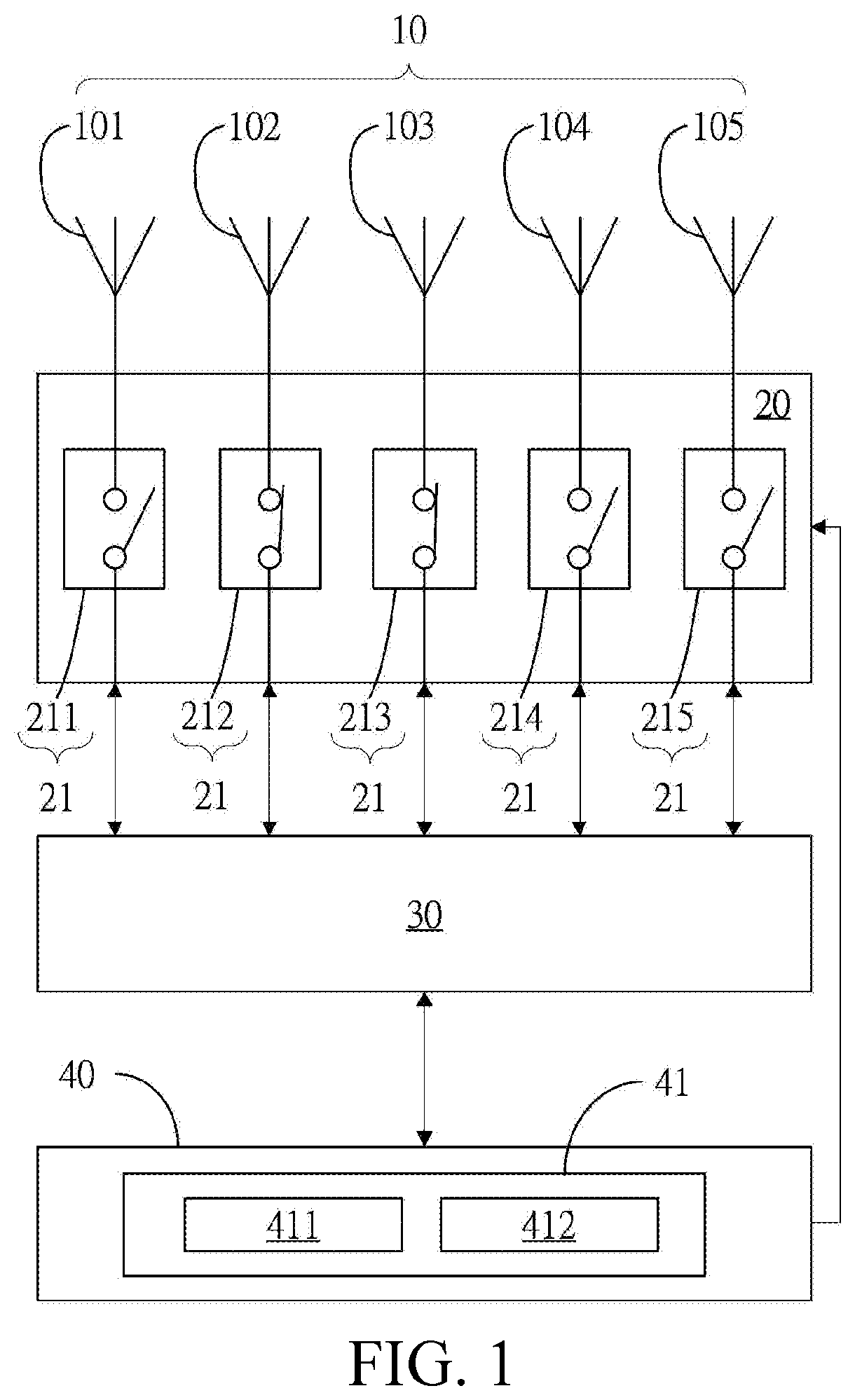
[0016]Referring to FIG. 1, an antenna system comprises a plurality of antennas 10, a switching unit 20, a communication unit 30 and a control unit 40. Each antenna 10 is connected with the switching unit 20. The control unit 40 is respectively connected with the switching unit 20 and the communication unit 30. The communication unit 30 is further connected with the switching unit 20.

[0017]In one embodiment, the antenna 10 receives and transmits a wireless signal.

[0018]Referring to FIG. 1, in this embodiment, the antenna system comprises five antennas 10 (101, 102, 103, 104 and 105), but which is not limited herein.

[0019]In some embodiments, each antenna 10 is any types of antenna, such as an omnibearing antenna or a directional antenna.

[0020]Referring to FIG. 1 and FIG. 2A, the switching unit 20 comprises a plurality of switches 21, and each switch 21 corresponds to one of the antennas 10. When the switch 21 is in a conducting state, the switch 21 is electrically connected with its ...


PUM


Abstract

An antenna system includes: a plurality of antennas; a switching unit, having a plurality of switches, wherein each of the plurality of switches and the corresponding antenna are in a conducting state or in a non-conducting state; a communication unit, connected with each of the plurality of switches of the switching unit, and coupled with the antennas, wherein the communication unit receives a reference value group of the corresponding antenna from the switch in the conducting state; and a control unit, connected with the switching unit and the communication unit, wherein the control unit receives the reference value group from the communication unit, and compares the reference value group with an threshold, to determine whether the reference value group conforms to a pre-determined condition or not, and outputs a restarting instruction to restart the switching unit when the reference value group does not satisfy the pre-determined condition.

Description

CROSS-REFERENCE TO RELATED APPLICATION[0001]This application claims the priority benefit of China Application Serial No. 201810525348.0 filed on May 28, 2018. The entirety of the above-mentioned patent application is hereby incorporated by reference herein and made a part of specification.BACKGROUND OF THE INVENTIONField of the Invention[0002]The invention relates to an antenna system.Description of the Related Art[0003]Along with scientific and technological progress, electronic devices are basically equipped with wireless communication modules. However, different environments bring different communication impacts. For example, a human body is close to an antenna, a long distance away from a base station, a direction deviation, or a shielding effect of room walls and the like. All the conditions above also affect a coverage rate of a multi-antenna radiation pattern. As a result, communication capacity of a communication device at a certain angle is weaker, even a dead angle of comm...

Claims


Application Information

Patent Timeline
IPC IPC(8): H04W72/08H04W16/28H04W64/00H01Q3/24H04W72/04
CPCH01Q21/29H01Q3/247H04B7/0814H01Q3/24H04B7/0691H04W16/28H04W72/0446H04W64/006H04W72/542
Inventor LIAO, ZIH-GUANGLIN, WEN-HSINTANG, CHING-CHUNGHSIEH, TSUNG-HSUNCHENG, YOU-FU
Owner ASUSTEK COMPUTER INC
Why Eureka
Try Eureka