Integrated pipe handling system for well completion and production

a technology of integrated pipes and handling systems, applied in the direction of drilling pipes, drilling rods, instruments, etc., can solve the problems of increasing profits, reducing drilling costs for drill operators, and difficulty in keeping track of individual pipes, so as to achieve the effect of not wasting time or effor

Inactive Publication Date: 2019-12-12
GLIDER PROD LLC
View PDF4 Cites 3 Cited by
  • Summary
  • Abstract
  • Description
  • Claims
  • Application Information

AI Technical Summary

Benefits of technology

[0014]A control system is also provided and may be used in a manual mode or an automatic mode to operate the movable containers and movable platform. In addition, information about each cylindrical object, such as its unique identifier, type, length, diameter and weight may be contained on a label, barcode, RFID tag or the like affixed to the object and may be recorded when the cylindrical objects are loaded into the movable containers. Information about the movable containers, such as a unique identifier, for example a number or alphanumeric code, may also be recorded. This information may be used to control the operation of the integrated system to ensure that the correct pipe is delivered to and removed from the drilling rig in the correct order without wasted time or effort.

Problems solved by technology

Doing so diminishes costs for the drill operator and thus increases profit, and may determine the economic viability of a particular well project.
This process makes it challenging to keep track of the individual pipes and the number of pipes ready for deployment into the well in an automated or centralized fashion.
It is also challenging to systematically or automatically control the order in which the pipes are added to the drill, casing or production string.
In addition, the size and weight of the pipes makes them potentially dangerous to the personnel working on or near the drilling rig.

Method used


Image

  • Integrated pipe handling system for well completion and production
  • Integrated pipe handling system for well completion and production
  • Integrated pipe handling system for well completion and production

Examples


Embodiment Construction

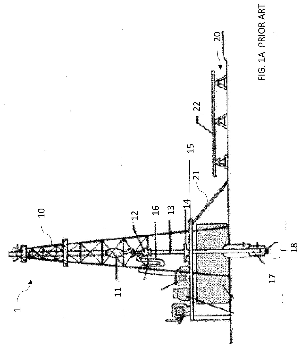
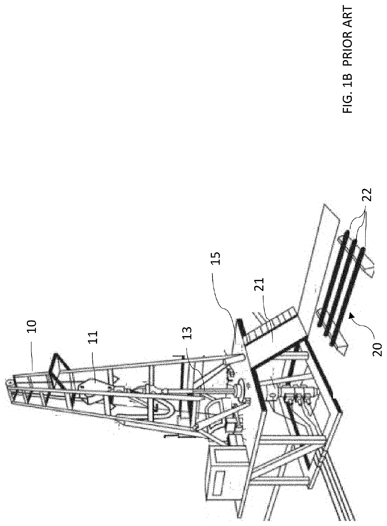
[0055]An exemplary drilling rig 1 is shown schematically in FIG. 1A. Drilling rig 1 includes derrick 10. Travelling block 11 is suspended from the top of derrick 10. A hook on the travelling block suspends a swivel 12, which is free to rotate in a horizontal plane. Alternatively, travelling block may suspend a direct drive motor (not shown). Kelly drive 13 is rotated by turntable 14 located on drilling rig floor 15 and engages the top of a drill joint through a bushing (not shown). Drilling fluid is pumped through the tubulars into the well via flexible hose 16. The drill string 17 is lowered into the well bore 18 as drilling proceeds. In later operations, casing joints and completion tubing is lowered into the well through the bore 18. Pipe rack 20 is located near derrick 10 and carries a plurality of pipes 22 typically arrayed horizontally as shown in FIG. 1B.

[0056]Pipe Tubs

[0057]In one embodiment of the integrated pipe handling system of the present invention, pipes are delivered...


PUM


Abstract

A novel integrated pipe handling system and method is provided wherein one or more pipe tubs having lift arms can be loaded with pipe and transported to a drill site where it may be deployed next to a pipe handling trailer. The pipe tubs and pipe handling trailer are arranged such that when the lift arms are raised, pipes may roll from a tub to the trailer, where a pipe is transferred to an angularly adjustable trough on the trailer. An inclinable transfer rack may be positioned adjacent the pipe handling trailer either with or without a tub located adjacent the inclinable transfer rack on the opposite side. The trough may be raised to a preselected position and the pipe moved along the trough by a skate such that the pipe is available to be transferred from the pipe handling trailer to a drilling rig. The process may be reversed to remove pipe from the drilling rig. A control system, which may be operated in a manual or automated mode, is used to operate the integrated system using information about each pipe joint recorded during the loading process. The length of each pipe transferred to the pipe handling trailer may be measured and tally information including the number and total length of pipe transferred may be displayed to an operator and downloaded to a memory.

Description

FIELD OF THE INVENTION[0001]This application is a continuation-in-part of U.S. patent application Ser. No. 16 / 003,240 filed Jun. 8, 2018, which is herein incorporated by reference in its entirety.[0002]The field of the invention relates to an integrated pipe handling system for use in oil and gas well drilling. In particular, the invention relates to an automated and integrated system for delivering pipe to a well in previously loaded containers, transferring the pipe to a pipe handling apparatus, and delivering the pipe to a drilling rig for use in drilling, casing and well completion operations. The automated and integrated system may also receive used pipe from the drilling rig and transfer the pipe from a pipe handling apparatus back to the containers for transport away from the well site.BACKGROUND OF THE INVENTION[0003]In the conventional drilling of an oil and gas well, a number of drill pipes (each approximately 30 feet in length) are connected together, for example by threa...

Claims


Application Information

Patent Timeline
Patent Type & Authority Applications(United States)
IPC IPC(8): E21B19/15G01B7/02G01B11/02
CPCE21B19/155G01B11/02G01B7/02E21B19/14E21B19/15
Inventor MCIVER, TERRY L.NASH, ZACHARY C.WEATHERMAN, GARY R.
Owner GLIDER PROD LLC
Why Eureka
Try Eureka