Original sheet dividing method and dividing mechanism and dividing apparatus therefor

a technology of dividing mechanism and dividing apparatus, which is applied in the direction of metal-working feeding device, soldering device, auxillary welding device, etc., can solve the problems of affecting the productivity of the machine, easy burrs at the cutting end face, and gradual wear of the cutting edge of the blade, so as to achieve the effect of avoiding time and effort for component replacemen

Inactive Publication Date: 2020-09-03
O M C
View PDF0 Cites 4 Cited by
  • Summary
  • Abstract
  • Description
  • Claims
  • Application Information

AI Technical Summary

Benefits of technology

[0046]According to the present invention, the original sheet can be cut while being conveyed, and a continuous operation can be enabled to be performed without occurrence of burrs at cut end faces, without scattering cutting dust, and without time and effort for component replacement.

Problems solved by technology

However, when the conventional dividing apparatus slits, with the disc-shaped slitter blades, an original sheet on which a hard active material is applied, the cutting edges of the blades is gradually worn by the hard active material, so that sharp burrs easily occur at cut end faces, that is, on the surface of the original sheet, in the cutting direction.
Thus, the burrs may repeatedly damage the separator, which is an insulating film, to cause flaws thereon to grow, or the burrs may grow, due to the above charging and discharging, to break through the separator to cause insulation breakdown, which causes trouble.
In addition to the above, in the case of cutting with blades, the conventional dividing apparatus requires periodical maintenance because of the wear as described above, and the apparatus has to be stopped for replacing the blades each time maintenance is performed, which becomes an obstacle to improvement of productivity.
As a result, the original sheet is not sufficiently cut, and its appearance is similar to that in the case where the laser beam merely runs over the original sheet.
When the above electronic component is produced by using the original sheet to which the fine particles have adhered, the adhering particles break the separator of the assembly during use of the electronic component to cause insulation breakdown, causing the same trouble as with the burrs.
However, an external force in the suction direction is momentarily applied to the melting material at start of the suction, so that part of the material scatters as fine dust to the surrounding area to adhere to the original sheet, causing the above trouble.

Method used


Image

  • Original sheet dividing method and dividing mechanism and dividing apparatus therefor
  • Original sheet dividing method and dividing mechanism and dividing apparatus therefor
  • Original sheet dividing method and dividing mechanism and dividing apparatus therefor

Examples


first embodiment

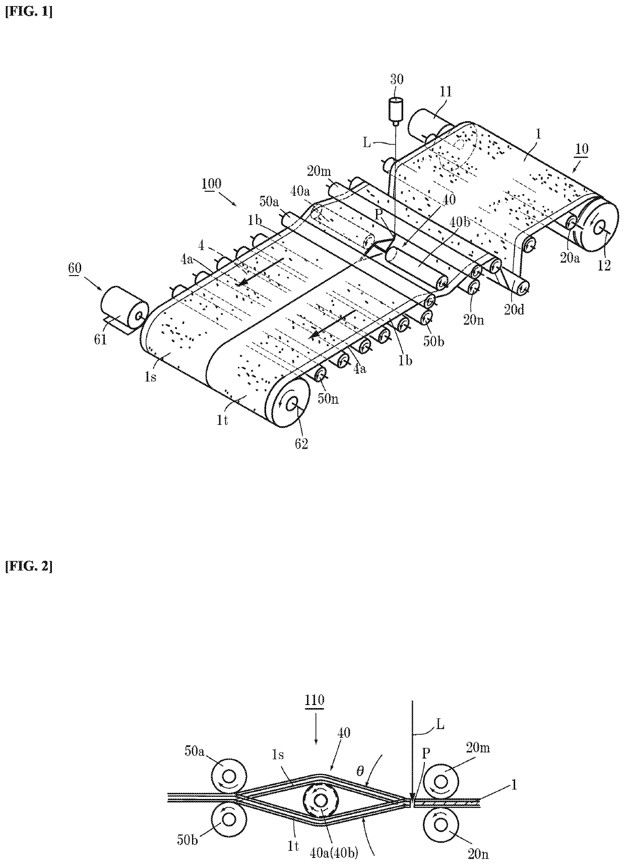
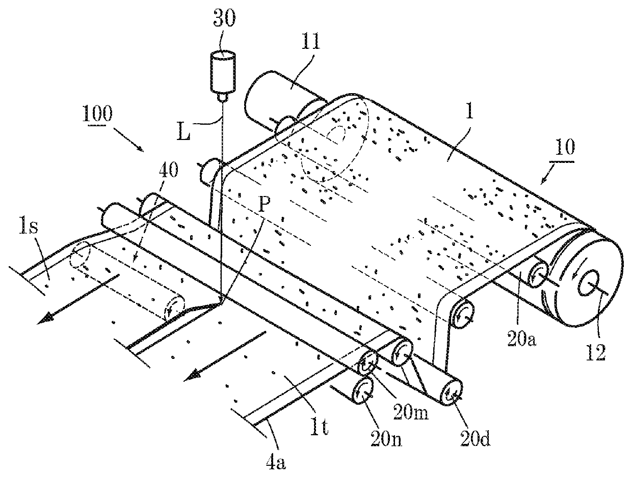
[0085]Next, operation of the apparatus 100 will be described. The original sheet 1 is mounted on the original sheet feed shaft 12 as shown in FIG. 1. In a drawn portion of the original sheet 1, a portion ahead of the irradiation point P of the laser beam L is divided into two divided original sheets 1s and 1t. The one divided original sheet 1s moves over the left separating roller 40a while the other original sheet 1t moves below the right separating roller 40b, and the original sheets 1s and 1t pass between the reception-side rollers 50a and 50b at the downstream side and are taken up on the take-up shaft 62.

[0086]When the apparatus 100 is actuated in this state, the feed-side servomotor 11 operates to feed the original sheet 1 at a predetermined speed. At the same time, the take-up servomotor 61 rotates in synchronization with the feed-side servomotor 11, so that the divided original sheets 1s and 1t are taken up.

[0087]In the division region, the laser beam L is emitted from the l...

second embodiment

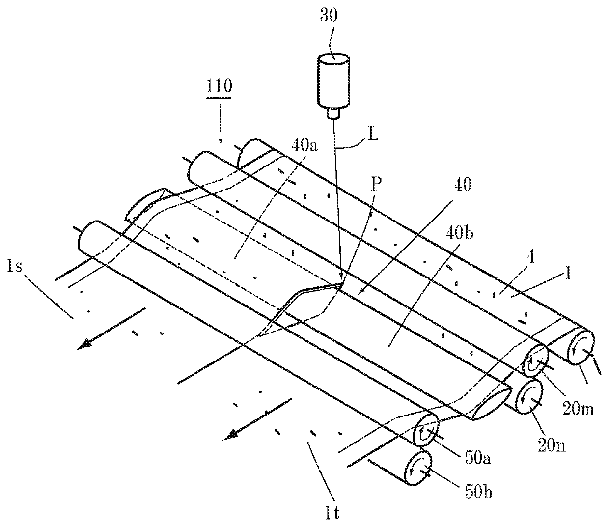
[0091]Next, a second embodiment will be described (FIGS. 3 and 4). As another example of the separating member 40, as shown in FIG. 3, the separating member 40 is composed of a plate-like member having a cross-section in the feed direction of the original sheet 1, the cross-section having a rhombic shape or a shape similar to a planar shape of a boat. That is, the separating member 40 is formed such that the side thereof close to the irradiation point P is formed in a thin blade shape and the thickness thereof gradually increases toward the opposite side. The center portion of the separating member 40 is thickest, and the thickness of the separating member 40 gradually decreases from the center portion toward the opposite side. A portion (left portion) of the plate-like separating member 40 is configured to be brought into sliding contact with the lower surface of the divided left original sheet 1s to raise the divided original sheet 1s. This portion is a raising portion 40a.

[0092]...

third embodiment

[0093]Next, the present invention will be described with reference to FIGS. 5 and 6. In this case, the single separating member 40 is provided as a roller type separating member 40 below the one divided original sheet 1s in the drawing so as to raise the original sheet 1s. The other divided original sheet 1t is fed with the height thereof maintained. Accordingly, a separation angle θ is formed between the original sheets 1s and 1t. In this case, the original sheet 1s after division is pulled closer to the division region side than the original sheet 1t by an amount by which the original sheet 1s is raised. Thus, the original sheets 1s and 1t are separately taken up. In this case as well, when the number of the divided sections is equal to or larger than 3, separating members 40 are disposed at alternate divided sections.

[0094]FIGS. 7 and 8 show a modification of the third embodiment of the present invention, and the separating member 40 is composed of the large-diameter portion 40a ...


PUM

PropertyMeasurementUnit
thicknessaaaaaaaaaa
energy densityaaaaaaaaaa
sizesaaaaaaaaaa

Abstract

Provided is an epoch-making original sheet dividing method in which an original sheet is cut while being conveyed and which enables a continuous operation to be performed for a long period of time without occurrence of burrs at cut end faces, without scattering cutting dust, and without time and effort for component replacement.The original sheet dividing method is an original sheet dividing method for cutting an original sheet 1 having an active material layer applied to at least one surface of a long metal foil 4, with a laser beam L in a longitudinal direction. The original sheet 1 is continuously moved. While the original sheet 1 is moved, the laser beam L is applied to the original sheet 1 to melt the original sheet 1 at an irradiation point P. At a downstream side of the irradiation point P of the laser beam L, one divided original sheet 1s is pulled upward relative to a feed surface of the original sheet 1, and adjacent another original sheet 1t is pulled downward relative to the feed surface of the original sheet 1, thereby separating the slit original sheets 1s and 1t adjacent to each other at the irradiation point P.

Description

TECHNICAL FIELD[0001]The present invention relates to an epoch-making original sheet dividing method that enables an original sheet for producing an electrode sheet used in a lithium secondary battery, a lithium capacitor, an electric double layer capacitor, and the like, to be divided into a plurality of sections with a laser beam, while the original sheet is being moved, without dust during being cut and without occurrence of burrs at cut end faces, and a dividing mechanism and a dividing apparatus therefor.BACKGROUND ART[0002]Nonaqueous electrolytic solution secondary batteries typified by lithium ion secondary batteries have been used in small electric apparatuses such as mobile phones and personal computers and in various large electric components such as electrical storage devices of hybrid or electric vehicles, since these secondary batteries have the merit of having a high energy density. Electrode assemblies that are main internal structures of lithium ion secondary batteri...

Claims


Application Information

Patent Timeline
Patent Type & Authority Applications(United States)
IPC IPC(8): B23K26/38B23K26/08B23K37/04B21D43/04H01M4/04
CPCB23K26/08B23K26/0853B23K2101/18B21D43/04B23K37/0408B23K26/38B23K26/0846B23K2101/34B23K26/0869B23K26/083B23K26/702
Inventor WATANABE, SHINJI
Owner O M C
Why Eureka
Try Eureka