Measuring arrangement in an injection-moulding system

a technology of measuring arrangement and injection moulding, which is applied in the direction of thermometers, instruments, transmission, etc., can solve the problem that commercially available elements cannot be used in measuring arrangement for the transmission of measurement data, and achieve the effect of easy cleaning and effort-free cleaning

Active Publication Date: 2010-09-30
KISTLER HLDG AG
View PDF1 Cites 5 Cited by
  • Summary
  • Abstract
  • Description
  • Claims
  • Application Information

AI Technical Summary

Benefits of technology

[0009]Because it is possible to separate the transmitter module and the receiving module from each other without force, these modules are not subjected to forces, in particular transversal forces, which otherwise might be applied during opening and lead to early damage of these modules. In addition, the planarity of the modules ensures that these modules do not engage and thereby damage each other. Another advantage of planarity is that planar surfaces can be kept clean easily and can be cleaned without effort. Since the modules are never pulled during separation, no force acts on their mounting elements and in no case on the cables connected thereto.
[0010]Another advantage of the measuring arrangement of the invention is that the modules can be disposed on a plane that has any desired orientation with respect to the direction of separation of the two mold components, i.e. base plate and mold insert. In particular, the separation plane can be in the direction of movement. In contrast, the above-mentioned prior art device must be located on a plane that is perpendicular to the direction of movement which is a considerable limitation.

Problems solved by technology

In many cases, commercially available elements cannot be used in measuring arrangements for the transmission of measurement data because they are much too big and / or too expensive, for example in injection molding systems having small cavities.

Method used


Image

  • Measuring arrangement in an injection-moulding system
  • Measuring arrangement in an injection-moulding system
  • Measuring arrangement in an injection-moulding system

Examples


Embodiment Construction

[0020]The reference numerals are the same in all Figures.

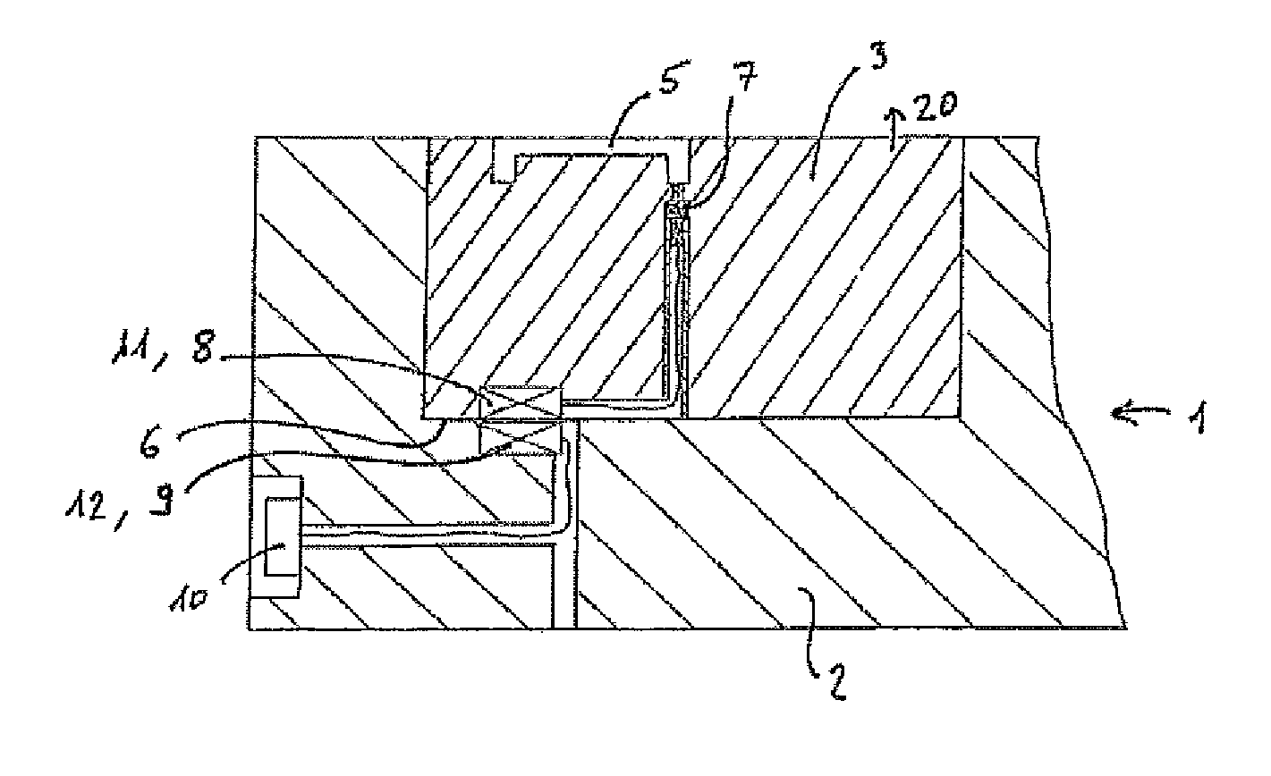
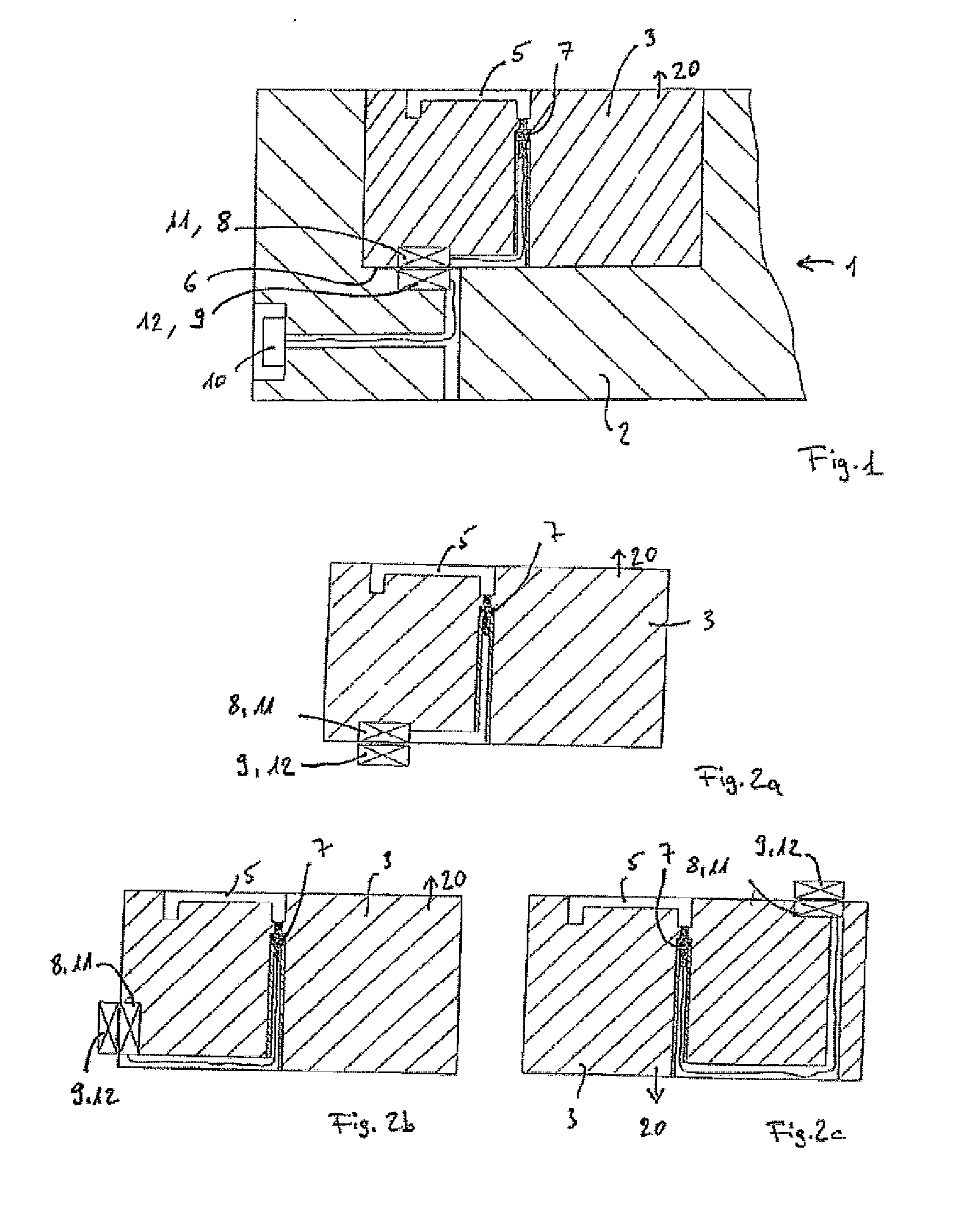
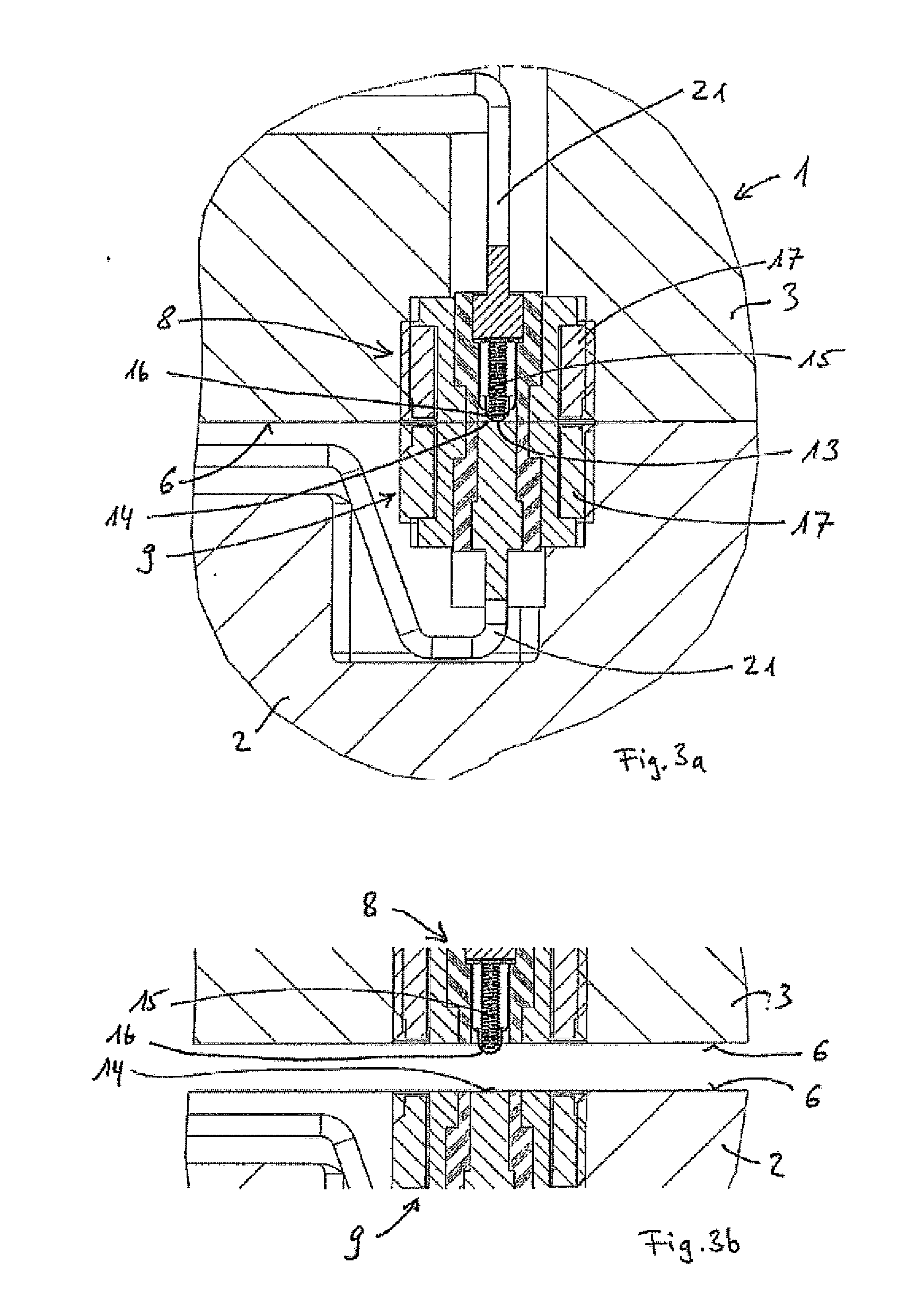
[0021]FIG. 1 shows a partial assembly of a portion of an injection molding system 1 comprising a base plate 2 and a mold insert with at least part of a cavity 5. The base plate 2 and the mold insert 3 are releasable from each other in a direction of movement 20 and have at least one common separation surface 6. Within the mold insert 3 is attached a sensor 7 for the detection of measurement data, for example pressures and / or temperatures, in the cavity 5. In particular, the sensor 7 can be a piezoelectric pressure sensor or a thermocouple. A transmitter module 8 in the mold insert 6 on the separation surface 6 is electrically connected to the sensor 7. In the base plate 2 also on the separation surface 6 and opposite the transmitter module 8 is attached a receiving module 9 whereby the transmitter module 8 can transmit measurement data acquired by the sensor 7 to the receiving module 9. The receiving module 9 is electrically c...


PUM

PropertyMeasurementUnit
pressuresaaaaaaaaaa
temperaturesaaaaaaaaaa
forceaaaaaaaaaa

Abstract

A measuring arrangement for measuring one or more pressures and/or temperatures in an injection-molding system includes a base plate and at least one mould insert with at least part of a cavity. The base plate and the mould insert rest against one another in a releasable manner on at least one common separating surface. The mould insert includes at least one sensor for detecting pressures and/or temperatures as well as a transmitter module on the separating surface, which transmitter module is electrically connected to the sensor. The base plate includes a receiving module on the separating surface opposite the transmitter module, wherein measurement data can be transmitted from the transmitter module to the receiving module. The transmitter module and the receiving module on the separating surface are essentially planar and can be separated without force

Description

CROSS-REFERENCE TO RELATED APPLICATIONS[0001]This application claims priority to International Application Serial No. PCT / CH2008 / 000418 filed Oct. 8, 2008, which claims priority to Swiss Application No. CH 01649 / 07 filed Oct. 22, 2007.TECHNICAL FIELD[0002]The invention relates to a measuring arrangement for measuring one or more pressures and / or temperatures in an injection-molding system.BACKGROUND[0003]Measuring arrangements are known to comprise a base plate and at least one mold insert with at least part of a cavity wherein the base plate and the mold insert rest against one another in a releasable manner on at least one common separation surface, as well as at least one sensor within the mold insert for the detection of pressures and / or temperatures wherein the measurement data can be transmitted from the base plate to an evaluation device. Measuring arrangements such as those described are routinely used in injection molding technology. In particular, the measuring arrangement...

Claims


Application Information

Patent Timeline
Patent Type & Authority Applications(United States)
IPC IPC(8): G01L7/00H04B5/00
CPCB29C45/77B29C45/78B29C2945/76006G01K1/14B29C2945/7626G01D21/02B29C2945/7604
Inventor WASER, MAXPLETSCHER, ERNST
Owner KISTLER HLDG AG
Why Eureka
Try Eureka