Piston pump for a vehicle brake system with a sealing element

a technology of sealing element and piston pump, which is applied in the direction of piston pumps, positive displacement liquid engines, liquid fuel engines, etc., can solve the problems of reducing the economic value affecting the performance of known piston pumps, and comparatively complex disassembly and disassembly of know piston pumps, so as to avoid damage to the inner wall of the cylinder or the effect of pistons

Active Publication Date: 2013-04-09
ROBERT BOSCH GMBH
View PDF16 Cites 4 Cited by
  • Summary
  • Abstract
  • Description
  • Claims
  • Application Information

AI Technical Summary

Benefits of technology

[0009]The object of the invention is to disclose a piston pump for a vehicle brake system that can be assembled and disassembled with little effort or expense and that can furthermore be manufactured economically.
[0011]According to the invention, the sealing element is embodied in one piece with the receiving element. This has the advantage that unlike the piston pumps known from the prior art, the functions of the sealing element and of the receiving element serving to receive the inlet valve are taken on by only a single component. Thus according to the invention, compared to the known embodiments, one less component is used, and as a consequence, the assembly and disassembly of the piston pump of the invention can be done very simply, and the chain of tolerances is reduced markedly. Moreover, by using one less component according to the invention, the manufacturing costs for the piston pump can be reduced markedly. Finally, because it uses one less component, the piston pump of the invention can be markedly smaller than known pumps.
[0012]In an advantageous refinement of the invention, the inlet valve has a valve seat, which is embodied on the piston rod. This structural embodiment according to the invention makes simple assembly and disassembly of the piston pump possible. Thus particularly for disassembling the piston pump, the piston rod adjoining the sealing element has to be removed from the sealing element. Next, the inlet valve, which is preferably embodied as a seat valve, can be removed together with its individual components, including in particular a barrier body and a spring element, without major effort or expense from the receiving element embodied in one piece with the sealing element. Finally, the sealing element, which is received longitudinally movably in the cylinder of the piston pump and on which the receiving element is embodied in one piece, can be removed from the cylinder without problems.
[0014]In a practical refinement of the invention, the sealing element is embodied in the form of a sealing ring with a sealing ring opening, and the piston rod is received in the sealing ring opening, and preferably the piston rod is received in the sealing ring opening with a clearance fit. By means of a clearance fit, the piston rod can be centered in the sealing ring opening without problems. Moreover, a clearance fit makes a requisite problem-free release of the piston rod from the sealing ring opening for disassembly purposes possible.
[0015]In a further advantageous refinement of the invention, a snap connection is embodied between the sealing element and the piston rod, for premounting the piston rod on the sealing element. The snap connection, which is preferably embodied on the sealing element, for instance embraces a shoulder embodied on the piston rod. By the snap connection according to the invention, during the assembly of the piston pump and in particular during the assembly on the cylinder, the piston rod can be held on the sealing element by way of the snap function furnished according to the invention. Moreover, by the snap connection according to the invention, the inner wall of the cylinder is protected from the outer diameter of the piston. By the snap connection of the invention, any contact of the piston with the inner wall of the cylinder is precluded so that damage to the inner wall of the cylinder or the piston is avoided.

Problems solved by technology

As a consequence, assembling and disassembling know piston pumps is comparatively complex.
Moreover, because of the many pump components provided, known piston pumps cannot be manufactured especially economically.

Method used


Image

  • Piston pump for a vehicle brake system with a sealing element
  • Piston pump for a vehicle brake system with a sealing element
  • Piston pump for a vehicle brake system with a sealing element

Examples


Embodiment Construction

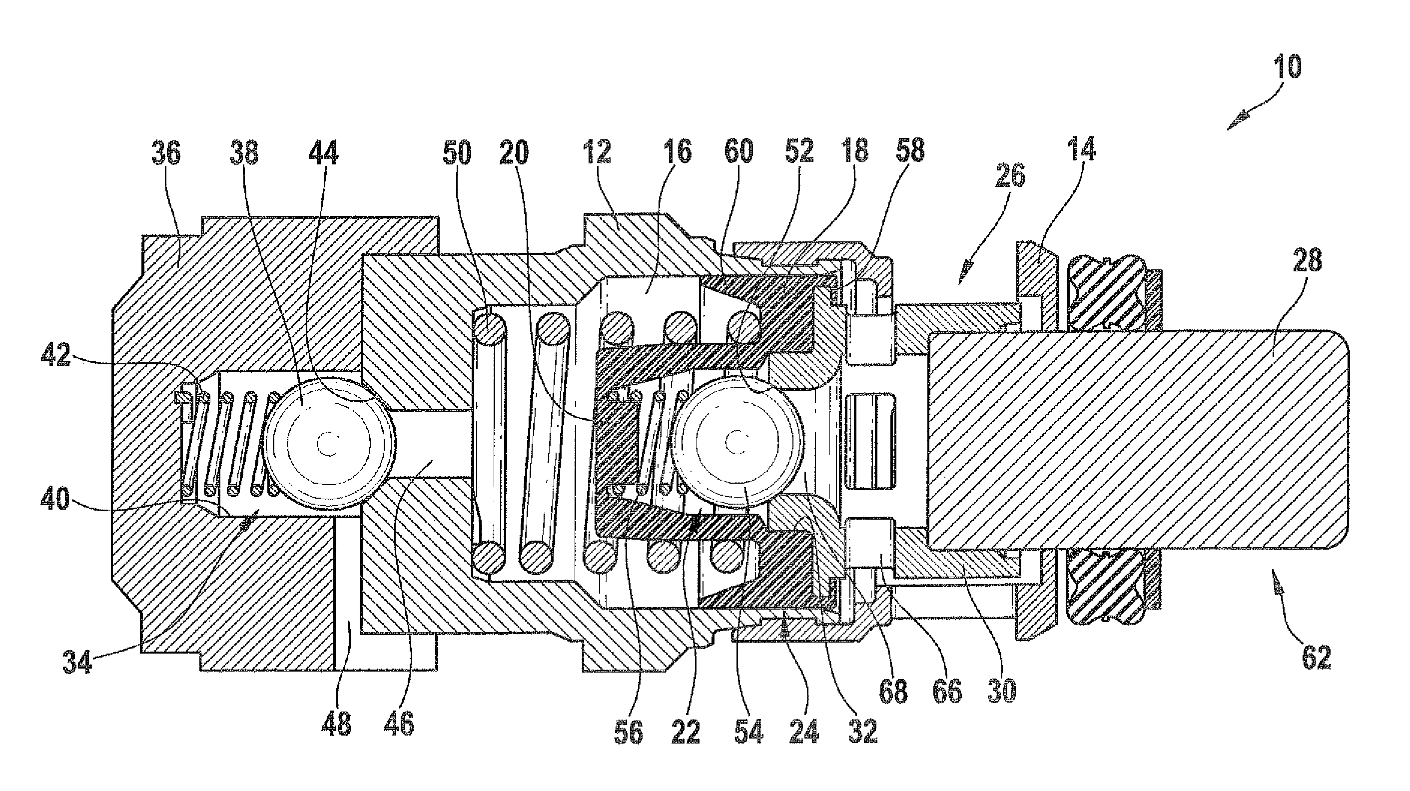
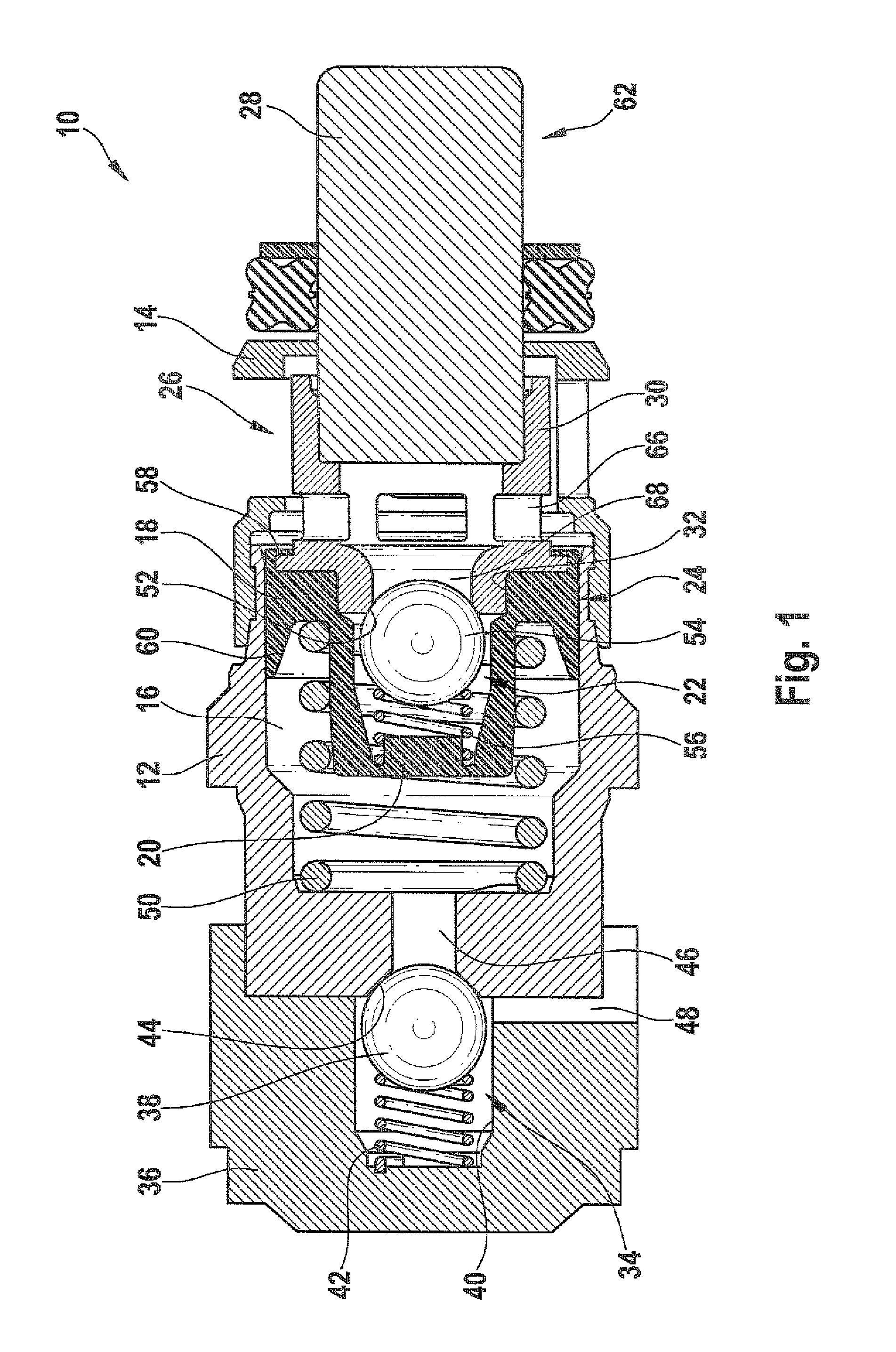
[0019]FIG. 1 shows a piston pump 10 according to the invention. The piston pump 10 includes two housing sections 12 and 14, and in the housing section 12, a cylinder bore 16 is embodied, in which a piston 26 is displaceably guided. The piston 26 includes a sealing element in the form of a sealing ring 18, a receiving element 20 for an inlet valve 22 that is embodied as a ball seat valve and is embodied in one piece with the sealing ring 18 and in the present case as an inlet valve cap, and a piston rod 62 that adjoins the sealing ring 18. The piston rod 62 is embodied in two parts and includes two piston rod elements 28, 30; the piston rod element 28 is received firmly in the piston rod element 30 by means of a press fit, in order to create a connection by nonpositive engagement between the two piston rod elements 28, 30. Because of the two-part embodiment of the piston rod 62 as provided, a piston rod 62 that can be manufactured economically is attained, since according to the inve...


PUM


Abstract

The invention relates to a piston pump for a vehicle braking system, with a housing section and a piston, which is guided in the housing section in a slidable manner. An accommodating member for accommodating an intake valve is provided in the housing section, and a sealing element adjoins the accommodating member to seal the piston against the housing section. A piston rod adjoins the sealing element which is embodied in one piece with the accommodating member.

Description

CROSS-REFERENCE TO RELATED APPLICATION[0001]This application is a 35 USC 371 application of PCT / EP 2007 / 054956 filed on May 22, 2007.BACKGROUND OF THE INVENTION[0002]1. Field of the Invention[0003]The invention relates to a piston pump for a vehicle brake system, having a housing section and a piston that is guided displaceably in the housing section, a receiving element for receiving an inlet valve, a sealing element adjoining the receiving element for sealing off the piston from the housing section, and a piston rod adjoining the sealing element.[0004]2. Description of the Prior Art[0005]The piston pumps for known vehicle brake systems, in particular anti-lock systems (ABS), serve to control the pressure in wheel brake cylinders. In the ABS, the piston pumps are intended for instance for returning brake fluid from one or more wheel brake cylinders to a master cylinder. Often, the ABS functions in combination with traction control (TC). Another known system, the electronic stabilit...

Claims


Application Information

Patent Timeline
Patent Type & Authority Patents(United States)
IPC IPC(8): F04B39/10F04B53/12
CPCB60T8/4031F04B1/0404F04B1/0448F04B1/04
Inventor SCHULLER, WOLFGANGZIMMERMANN, MARC
Owner ROBERT BOSCH GMBH
Why Eureka
Try Eureka