Information processing apparatus and non-transitory computer readable medium

Pending Publication Date: 2019-12-12
FUJIFILM BUSINESS INNOVATION CORP
0 Cites 0 Cited by

AI-Extracted Technical Summary

Problems solved by technology

However, aspects of the non-limiting embodiments are not required to address the advantages described above, an...

Method used

[0095]In a case where the presentation software C, the audio device E, and the projector D are identified as the collaboration candidates in the above manner, the control unit 24 causes information to be displayed on the screen 40, the information providing guides to these configurations. In this exemplary case, the collaborative function is a function of opening a file B stored in the laptop PC (A) by using the presentation software C, projecting an image by using the projector D, and playing back audio information by using the audio device E. Note that the presentation software C is installed in the laptop PC (A). In this collaborative function, the presentation software C installed in the laptop PC (A) is executed, and subsequently, the functions of the projector D and the audio device E are executed. That is, the laptop PC (A) and the presentation software C each correspond to a first-level configuration, and the projector D and the audio device E each correspond to a second-level configuration. In this case, the control unit 24 provides guides to the configurations in accordance with the level (order of execution). Specifically, the control unit 24 causes images 76, 78, and 80 to be displayed on the screen 40. The image 76 represents an arrow connecting the image 48, which is associated with the laptop PC (A), and the image 58, which is associated with the presentation software C, to each other (the image 76 represents an arrow extending from the image 48 to the image 58). The image 78 represents an arrow connecting the image 58, which is associated with the presentation software C, and the image 50, which is associated with the audio device E, to each other (the image 78 represents an arrow extending from the image 58 to the image 50). The image 80 represents an arrow connecting the image 58, which is associated with the presentation software C, and an image 74, which is associated with the projector D, to each other (the image 80 represents an arrow extending from the image 58 to the image 74). Display of such arrow images represents execution of the presentation software C installed in the laptop PC (A), followed by execution of processes of the audio device E and the projector D. This makes it possible to provide the order of processes to the user with high visibility.
[0101]Even in a case where a collaborative function that is executable by causing the laptop PC (A) and the multi-function peripheral associated with the image 46 to work in collaboration with each other is registered in the collaboration function management table, for example, if the laptop PC (A) and the multi-function peripheral have never worked in collaboration with each other or the collaboration frequency is lower than the threshold, the identification unit 26 does not identify the multi-function peripheral as a collaboration candidate. As a result, an...

Benefits of technology

[0007]According to an aspect of the present disclosure, there is provided an information processing apparatus including a control unit. In a case where a plurality of configurations are present as collaboration candidates and a ...

Abstract

An information processing apparatus comprising includes a control unit. In a case where plural configurations are present as collaboration candidates and plural combinations of configurations that are required for executing a collaborative function are present, the control unit controls providing a notification of at least one combination among the plural combinations.

Application Domain

Pictoral communicationDigital output to print units

Technology Topic

CollaborationControl unit +2

Image

  • Information processing apparatus and non-transitory computer readable medium
  • Information processing apparatus and non-transitory computer readable medium
  • Information processing apparatus and non-transitory computer readable medium

Examples

  • Experimental program(7)

Example

FIRST EXAMPLE
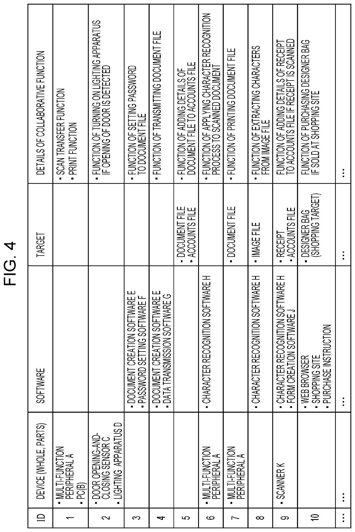
[0086]Now, a first example will be described with reference to FIG. 6. FIG. 6 illustrates the screen 40. For example, if a user specifies the image 56 associated with email software by operating the UI unit 20, by referring to the collaborative function management table, the identification unit 26 identifies configurations (the devices 12, software, targets) that are usable for executing a collaborative function in collaboration with the email software. In an exemplary case, the email software is installed in a laptop PC (A) associated with the image 48, and a function (collaborative function) of sending email by using the laptop PC (A) and the email software is registered in the collaborative function management table. In this case, the identification unit 26 identifies the laptop PC (A) as a collaboration candidate. Note that information indicating software that is installed in each of the devices 12 is registered in advance in the collaborative function management table.
[0087]In a case where the laptop PC (A) is identified as the collaboration candidate in the above manner, the control unit 24 controls providing a guide to the laptop PC (A). For example, the control unit 24 causes an image 70 to be displayed on the screen 40. The image 70 represents an arrow extending from the image 56 specified by the user to the image 48 associated with the laptop PC (A). That is, the control unit 24 causes the image 70 of the arrow to be displayed on the screen 40, the arrow connecting the image 56 and the image 48 to each other. In addition, the control unit 24 causes a display frame 72 to be displayed on the screen 40 in association with the image 48, and also causes information to be displayed within the display frame 72, the information indicating details of the collaborative function that is executable by using the laptop PC (A) and the email software.
[0088]For example, if the user specifies the display frame 72 by operating the UI unit 20 (e.g., if the user clicks the display frame 72), the control unit 24 sets the collaborative function for the laptop PC (A). For example, the control unit 24 transmits control information indicating the collaborative function to the laptop PC (A). On the basis of the control information, the laptop PC (A) starts the email software installed in the laptop PC (A). Thus, the user can create email by using the laptop PC (A).
[0089]In a case where the email software is not installed in the laptop PC (A), the control unit 24 does not cause the guide to the laptop PC (A) to be displayed. Even in a case where the email software is not installed in the laptop PC (A), as long as it is possible to install the email software in the laptop PC (A), the control unit 24 may cause information thereof to be displayed on the screen 40.
[0090]In addition, although the image 46 associated with the multi-function peripheral and the image 50 associated with the audio device are displayed on the screen 40, the multi-function peripheral and the audio device are not registered in the collaborative function management table as the devices 12 that are usable for executing a collaborative function in collaboration with the email software specified by the user. Thus, the control unit 24 does not cause a guide to the multi-function peripheral and a guide to the audio device to be displayed.
[0091]In the above example, the email software and the laptop PC (A) correspond to a combination of configurations that are required for executing a collaborative function, and the combination is displayed by using the image 70 of the arrow. Note that the control unit 24 may output information (e.g., a name) for identifying the laptop PC (A) as audio information from a speaker in place of, or in addition to, display of the image 70 of the arrow. Besides the display of the arrow image, the control unit 24 may enlarge an image that is a guide target (e.g., the image 48) displayed on the screen 40.
[0092]A notification of the combination of configurations that are required for executing a collaborative function is provided in the above manner, and thus, the user can recognize the configurations with ease.

Example

SECOND EXAMPLE
[0093]Now, a second example will be described with reference to FIG. 7. FIG. 7 illustrates the screen 40. In the second example, the control unit 24 provides guides to configurations in accordance with the order of use in a collaborative function. The control unit 24 may provide guides to configurations in accordance with the order of processes in the collaborative function or may provide guides to configurations in accordance with the order of use of data. For example, a device that stores data to be used for the collaborative function corresponds to a higher-order configuration, and a device 12 or software that uses the data corresponds to a lower-order configuration. It is needless to say that this is merely an example, and the order may be determined by other criteria.
[0094]For example, if a user specifies the image 48 associated with the laptop PC (A) by operating the UI unit 20, by referring to the collaborative function management table, the identification unit 26 identifies configurations (the devices 12, software, targets) that are usable for executing a collaborative function in collaboration with the laptop PC (A). In an exemplary case, a collaborative function that is executable by using the laptop PC (A), presentation software C, an audio device E, and a projector D is registered in the collaborative function management table. In this case, the identification unit 26 identifies the presentation software C, the audio device E, and the projector D as collaboration candidates.
[0095]In a case where the presentation software C, the audio device E, and the projector D are identified as the collaboration candidates in the above manner, the control unit 24 causes information to be displayed on the screen 40, the information providing guides to these configurations. In this exemplary case, the collaborative function is a function of opening a file B stored in the laptop PC (A) by using the presentation software C, projecting an image by using the projector D, and playing back audio information by using the audio device E. Note that the presentation software C is installed in the laptop PC (A). In this collaborative function, the presentation software C installed in the laptop PC (A) is executed, and subsequently, the functions of the projector D and the audio device E are executed. That is, the laptop PC (A) and the presentation software C each correspond to a first-level configuration, and the projector D and the audio device E each correspond to a second-level configuration. In this case, the control unit 24 provides guides to the configurations in accordance with the level (order of execution). Specifically, the control unit 24 causes images 76, 78, and 80 to be displayed on the screen 40. The image 76 represents an arrow connecting the image 48, which is associated with the laptop PC (A), and the image 58, which is associated with the presentation software C, to each other (the image 76 represents an arrow extending from the image 48 to the image 58). The image 78 represents an arrow connecting the image 58, which is associated with the presentation software C, and the image 50, which is associated with the audio device E, to each other (the image 78 represents an arrow extending from the image 58 to the image 50). The image 80 represents an arrow connecting the image 58, which is associated with the presentation software C, and an image 74, which is associated with the projector D, to each other (the image 80 represents an arrow extending from the image 58 to the image 74). Display of such arrow images represents execution of the presentation software C installed in the laptop PC (A), followed by execution of processes of the audio device E and the projector D. This makes it possible to provide the order of processes to the user with high visibility.
[0096]In addition, the control unit 24 causes a display frame 82 to be displayed on the screen 40 in association with the image 48, and also causes information to be displayed within the display frame 82, the information indicating details of the above collaborative function. For example, if the user specifies the display frame 82 by operating the UI unit 20 (e.g., if the user clicks the display frame 82), the control unit 24 sets the collaborative function for the laptop PC (A), the presentation software C, the projector D, and the audio device E. For example, the control unit 24 transmits control information indicating the collaborative function to the laptop PC (A), the projector D, and the audio device E. On the basis of the control information, each of the laptop PC (A), the projector D, and the audio device E executes an assigned process.
[0097]As another example, in a case where the presentation software C is installed in the terminal apparatus 10, the presentation software C installed in the terminal apparatus 10 may be used for the above collaborative function. In this exemplary case, the file B stored in the laptop PC (A) is transmitted from the laptop PC (A) to the terminal apparatus 10, the file B is opened in the terminal apparatus 10 by using the presentation software C, and further, the file B is transmitted from the terminal apparatus 10 to the projector D and the audio device E. Then, an image included in the file B is projected by using the projector D, and audio information included in the file B is played back by using the audio device E. Also in this case, since the file B is transmitted in the order of the laptop PC (A), the terminal apparatus 10, the projector D, and the audio device E, the arrow images represent the order of processes on the file B or the order of use of the file B. In this case, the laptop PC (A) corresponds to the first-level configuration, the presentation software C installed in the terminal apparatus 10 corresponds to the second-level configuration, and the projector D and the audio device E each correspond to a third-level configuration.
[0098]Alternatively, the identification unit 26 may identify a collaboration candidate on the basis of a use history of the configurations, compatibility between the configurations, or the user's use trend.
[0099]For example, the use history of the configurations is managed, and information indicating the use history is stored in the terminal apparatus 10, the devices 12, or an external apparatus such as a server. In addition, for each configuration, a history of collaboration with another configuration is managed as a use history, and information indicating the use history is stored in the terminal apparatus 10, the devices 12, or an external apparatus such as a server. By referring to the information indicating the use history, the identification unit 26 of the terminal apparatus 10 may identify, as a collaboration candidate, another configuration that has worked in collaboration with the configuration specified by the user, another configuration whose collaboration frequency (e.g., the total number of times of collaboration or the number of times of collaboration per unit period) is higher than or equal to a threshold, or another configuration whose level determined by the collaboration frequency is high. The higher the frequency is, the higher the level is.
[0100]A specific example will be described. In a case where a user specifies the laptop PC (A), if the frequency of collaboration of the laptop PC (A) and the presentation software C is higher than or equal to the threshold, the identification unit 26 identifies the presentation software C as a collaboration candidate. As another example, if the collaboration frequency is the highest or a level determined by the collaboration frequency is higher than or equal to a predetermined level, the identification unit 26 identifies the presentation software C as a collaboration candidate. The same applies to the projector D and the audio device E. This makes it possible to present to the user, a configuration having a high possibility to be used in collaboration with the laptop PC (A) specified by the user.
[0101]Even in a case where a collaborative function that is executable by causing the laptop PC (A) and the multi-function peripheral associated with the image 46 to work in collaboration with each other is registered in the collaboration function management table, for example, if the laptop PC (A) and the multi-function peripheral have never worked in collaboration with each other or the collaboration frequency is lower than the threshold, the identification unit 26 does not identify the multi-function peripheral as a collaboration candidate. As a result, an arrow image pointing at the image 46 is not displayed. This makes it possible to prevent a configuration having a low possibility to be used in collaboration with the laptop PC (A) from being presented to the user.
[0102]That is, combinations of configurations that are usable for executing a collaborative function include a combination of the laptop PC (A) and the multi-function peripheral, a combination of the laptop PC (A) and the presentation software C, a combination of the laptop PC (A) and the projector D, a combination of the laptop PC (A) and the audio device E, and a combination of the laptop PC (A) and a plurality of configurations. From among the plurality of combinations, at least one combination is presented to the user. For example, as in the above case, a combination is identified on the basis of the use history, and the identified combination is presented to the user.
[0103]The above use history may be managed for each user or each user account, and information indicating the use history of each user or each user account may be stored in the terminal apparatus 10, the devices 12, or an external apparatus such as a server. The use history corresponds to the user's or the user account's use trend. For example, by referring to the information indicating the use history of a user who has logged in to the terminal apparatus 10 or a user account, the identification unit 26 may identify, as a collaboration candidate, another configuration that has worked in collaboration with the configuration specified by the user or may identify the collaboration candidate on the basis of the collaboration frequency. Thus, the collaboration candidate in accordance with the user's use trend is presented to the user.
[0104]The identification unit 26 may also identify the collaboration candidate on the basis of the compatibility between the configurations. The compatibility is determined in advance on the basis of, for example, the number of collaborative functions that are executable by using the configurations, and information indicating the compatibility is registered in advance in the collaborative function management table. For example, in a case where the number of collaborative functions that are executable by using the laptop PC (A) and the presentation software C is greater than or equal to a threshold, the identification unit 26 identifies the presentation software C as the collaboration candidate. On the other hand, in a case where the number of collaborative functions that are executable by using the laptop PC (A) and the multi-function peripheral is less than the threshold, the identification unit 26 does not identify the multi-function peripheral as the collaboration candidate. A guide (arrow image) to the presentation software C is displayed on the screen 40 whereas a guide to the multi-function peripheral is not displayed on the screen 40. This makes it possible to present to the user, a collaboration candidate with which the number of collaborative functions is greater than or equal to the threshold.
[0105]From among the configurations (the device 12, software, targets) displayed on the screen 40, the identification unit 26 may identify, as the collaboration candidate, another configuration having a higher level that is determined by the number of executable collaborative functions. The larger the number is, the higher the order is. For example, in a case where the number of collaborative functions that are executable by using the laptop PC (A) and the presentation software C is the largest or the level determined by the number is higher than or equal to a predetermined level, the identification unit 26 identifies the presentation software C as the collaboration candidate. The same applies to the projector D and the audio device E. Even in a case where collaborative functions that are executable by causing the laptop PC (A) and the multi-function peripheral to work in collaboration with each other are registered in the collaborative function management table, if the level determined by the number of collaborative functions is lower than the predetermined level, the identification unit 26 does not identify the multi-function peripheral as the collaboration candidate.
[0106]Note that the compatibility between the configurations may be determined by a factor other than the number of collaborative functions. For example, the compatibility between the configurations may be determined by performance of the devices 12, performance of the software, a standard of the devices 12, a standard of the software, a manufacturer, a version, and so on.
[0107]If a configuration included in a combination of configurations is specified by the user, the control unit 24 does not have to display a guide to the specified configuration. This process will be described with reference to FIG. 8. FIG. 8 illustrates the screen 40. For example, if a user specifies the image 58 associated with the presentation software C as a second-level configuration, the control unit 24 hides from display, the image 76 of the arrow connecting the image 48, which is associated with the laptop PC (A), and the image 58 to each other. Thus, the user can recognize that the image 58 is specified by the user. Also in this case, the control unit 24 causes a guide from the second-level configuration to a third-level configuration to be displayed on the screen 40. In the example illustrated in FIG. 8, the control unit 24 causes the image 78 of the arrow to be displayed on the screen 40, the arrow connecting the image 58, which is associated with the presentation software C, and the image 50, which is associated with the audio device E, to each other. The same applies to the image 80 that provides a guide to the projector D.

Example

THIRD EXAMPLE
[0108]Now, a third example will be described with reference to FIG. 9. FIG. 9 illustrates the screen 40. In the third example, if a user specifies a configuration, the control unit 24 causes a list of functions of the specified configuration to be displayed on the screen 40, and provides a notification of a combination of configurations in units of functions included in the list. A specific example will be described below.
[0109]As illustrated in FIG. 9, if the user specifies the image 48 associated with the laptop PC (A) by operating the UI unit 20, the control unit 24 causes a list 84 of functions of the laptop PC (A) to be displayed on the screen 40. Note that the functions of the devices 12 and the pieces of software are registered in the collaborative function management table in advance, for example, and by referring to the collaborative function management table, the control unit 24 identifies the functions of the configuration specified by the user. For example, computer-aided design (CAD) software (e.g., drawing software), video editing software, audio playback software, and the like are installed in the laptop PC (A), and the laptop PC (A) has functions to be implemented by the pieces of software.
[0110]Subsequently, by referring to the collaborative function management table, the identification unit 26 identifies configurations (the device 12, software, targets) that are usable for executing a collaborative function in collaboration with a function included in the list 84. In an exemplary case, a function (collaborative function) of transferring data by email by using the CAD software and email software, the data having been created by using the CAD software, is registered in the collaborative function management table. In this case, the identification unit 26 identifies the CAD software and the email software as collaboration candidates. Note that the email software may be installed in the laptop PC (A) or may be installed in the terminal apparatus 10.
[0111]In a case where the CAD software and the email software are identified as the collaboration candidates in the above manner, the control unit 24 controls providing a guide from the CAD software to the email software. For example, the control unit 24 causes an image 86 to be displayed on the screen 40. The image 86 represents an arrow extending from a character string indicating the CAD software in the list 84 to the image 56 associated with the email software. That is, the control unit 24 causes the image 86 of the arrow to be displayed on the screen 40, the arrow connecting the character string indicating the CAD software and the image 56 to each other. This makes it possible to present the collaboration candidates to the user by using the list of functions and the image associated with the configuration. In addition, the control unit 24 causes a display frame 88 to be displayed on the screen 40 in association with the character string indicating the CAD software. The control unit 24 also causes information to be displayed within the display frame 88, the information indicating details of the collaborative function that is executable by using the CAD software and the email software.
[0112]For example, if the user specifies the display frame 88 by operating the UI unit 20, the control unit 24 sets the collaborative function for the laptop PC (A) and transmits control information indicating the collaborative function to the laptop PC (A). In accordance with the control information, the laptop PC (A) transfers data created by using the CAD software installed in the laptop PC (A) to a destination by email created by using the email software installed in the laptop PC (A).
[0113]In a case where the email software installed in the terminal apparatus 10 is used for the collaborative function, the control unit 24 sets the collaborative function for the laptop PC (A) and the terminal apparatus 10. The laptop PC (A) transmits data created by using the CAD software to the terminal apparatus 10. The control unit 24 of the terminal apparatus 10 transfers the data to a destination by email created by using the email software installed in the terminal apparatus 10.
[0114]In a case where a plurality of combinations of configurations that are usable for executing a collaborative function are present, the control unit 24 may control guides to the plurality of combinations. This process will be described with reference to FIG. 10. FIG. 10 illustrates an example of the screen 40. In an exemplary case, a transfer function (collaborative function) and a playback function (collaborative function) are registered in the collaborative function management table. The transfer function is a function of transferring data by email by using the CAD software and the email software included in the list 84, the data having been created by using the CAD software. The playback function is a function of playing back music data by using music playback software and the audio device E included in the list 84. In this case, the identification unit 26 identifies a combination (first combination) of the CAD software and the email software and a combination (second combination) of the music playback software and the audio device E as collaboration candidates. This makes it possible to present the plurality of combinations of collaboration candidates to the user by using the list of functions and the images associated with the configurations.
[0115]In a case where the first combination and the second combination are identified as in the above case, the control unit 24 controls a guide from the CAD software to the email software as a guide to the first combination, and controls a guide from the music playback software to the audio device E as a guide to the second combination. For example, the control unit 24 causes the image 86 of the arrow to be displayed on the screen 40, the arrow extending from the character string indicating the CAD software in the list 84 to the image 56 associated with the email software. In addition, the control unit 24 causes an image 90 to be displayed on the screen 40. The image 90 represents an arrow extending from a character string indicating the music playback software in the list 84 to the image 50 associated with the audio device E. Furthermore, the control unit 24 causes the display frame 88 and a display frame 92 to be displayed on the screen 40. The display frame 88 is associated with the character string indicating the CAD software, and the display frame 92 is associated with the character string indicating the music playback software. The control unit 24 also causes information to be displayed within the display frame 88, the information indicating details of the collaborative function that is executable by using the CAD software and the email software, and causes information to be displayed within the display frame 92, the information indicating details of the collaborative function that is executable by using the music playback software and the audio device E. As in the second example, the collaborative functions are set for the configurations by a user operation and executed.
[0116]Alternatively, a plurality of lists may be displayed on the screen 40, and guides may be displayed between the lists. This process will be described with reference to FIG. 11. FIG. 11 illustrates an example of the screen 40. For example, if a user specifies the image 46 associated with the multi-function peripheral, the control unit 24 causes a list 94 of functions of the multi-function peripheral to be displayed on the screen 40 in association with the image 46. By referring to the collaborative function management table, the identification unit 26 identifies another configuration that is usable for executing a collaborative function in collaboration with the multi-function peripheral. For example, in a case where the other configuration is the laptop PC (A), the control unit 24 causes the list 84 of functions of the laptop PC (A) to be displayed on the screen 40 in association with the image 48. The functions of the multi-function peripheral and the functions of the laptop PC (A) are, for example, registered in advance in the collaborative function management table. Note that the list 94 corresponds to an example of a first list, and the list 84 corresponds to an example of a second list.
[0117]In addition, the identification unit 26 identifies a function that is included in the list 84 and that is usable for executing a collaborative function in collaboration with a function included in the list 94. In an exemplary case, a storage function (collaborative function) is registered in the collaborative function management table. The storage function is a function of storing data that is scanned by using the multi-function peripheral in a folder of document management software by using a scan function included in the list 94 and document management software included in the list 84. In this case, the identification unit 26 identifies a combination of the scan function and the document management software as collaboration candidates.
[0118]In a case where the combination is identified in the above manner, the control unit 24 controls a guide from the scan function to the document management software as a guide to the combination. For example, the control unit 24 causes an image 96 to be displayed on the screen 40. The image 96 represents an arrow extending from a character string indicating the scan function in the list 94 to a character string indicating the document management software in the list 84. This makes it possible to present the collaboration candidates to the user by using the plurality of lists. In addition, the control unit 24 causes a display frame 97 to be displayed on the screen 40 in association with the character string indicating the scan function. The control unit 24 also causes information to be displayed within the display frame 97, the information indicating details of the collaborative function that is executable by using the scan function and the document management software. As in the second example, the collaborative function is set for the configurations by a user operation and executed.
[0119]Although the lists of functions of the devices 12 are displayed in the above example, in a case where software corresponds to a collaboration candidate, a list of functions of the software may be displayed, and a guide to a function included in the list may be displayed.
[0120]In addition, images associated with the functions of the devices 12 or the software may be displayed on the screen 40. This display example will be described with reference to FIG. 12. FIG. 12 illustrates an example of the screen 40.
[0121]As an example, in the main display region 42 of the screen 40, the image 48 associated with the laptop PC (A) and the image 46 associated with the multi-function peripheral are displayed. The control unit 24 causes a function image group 98 to be displayed around the image 46 associated with the multi-function peripheral. The function image group 98 represents a group of functions of the multi-function peripheral. The function image group 98 includes function images 100, 102, 104, and the like. The function image 100 is associated with a print function of the multi-function peripheral. The function image 102 is associated with a facsimile function of the multi-function peripheral. The function image 104 is associated with a scan function of the multi-function peripheral. Likewise, the control unit 24 causes a function image group 106 to be displayed around the image 48 associated with the laptop PC (A). The function image group 106 represents a group of functions of the laptop PC (A). The function image group 106 includes function images 108, 110, 112, and 114, and the like. The function image 108 is associated with a download function of the laptop PC (A). The function image 110 is associated with an upload function of the laptop PC (A). The function image 112 is associated with a web browser function of the laptop PC (A). The function image 114 is associated with a music playback function of the laptop PC (A).
[0122]The control unit 24 causes the function images included in the function image group 98 to be displayed on the screen 40 so as to circulate in the direction indicated by arrows at a predetermined speed. In a case where not all of the function images included in the function image group 98 are displayed on the screen 40, function images at early orders are displayed whereas function images at later orders are not displayed. As the function images circulate, the function images at early orders disappear from the screen 40 to transition to the function images at later orders, and the function images at later orders transition to the function images at early orders on the screen 40. The same applies to the function image group 106. This way of display makes it possible to present a larger number of function images to the user on the screen having a limited space.
[0123]The control unit 24 may cause the function image group 98 to be displayed on the screen 40 if the user specifies the image 46. Alternatively, the control unit 24 may cause the function image group 98 to be displayed on the screen 40 even if the user does not specify the image 46. The same applies to the function image group 106.
[0124]In a case where the user specifies the image 46, if the laptop PC (A) is registered in the collaborative function management table as a configuration that is usable for executing a collaborative function in collaboration with the multi-function peripheral, which is associated with the image 46, the control unit 24 may cause the function image group 106 regarding the laptop PC (A) to be displayed on the screen 40.
[0125]For example, if the user specifies the function image 104 associated with the scan function of the multi-function peripheral, by referring to the collaborative function management table, the identification unit 26 identifies configurations (the devices 12, software, targets) that are usable for executing a collaborative function in collaboration with the scan function, and further identifies a function (a function of a device 12 or software) that is executable in collaboration with the scan function. For example, in a case where the download function of the laptop PC (A) is registered in the collaborative function management table as a function that is usable for executing a collaborative function in collaboration with the scan function, the identification unit 26 identifies the download function as a collaboration candidate.
[0126]In a case where the collaboration candidate is identified in the above manner, the control unit 24 provides a guide to the collaboration candidate. For example, the control unit 24 causes an image 116 to be displayed on the screen 40. The image 116 represents an arrow extending from the function image 104 associated with the scan function to the function image 108 associated with the download function. In addition, the control unit 24 causes a display frame 117 to be displayed on the screen 40, and also causes information to be displayed within the display frame 117, the information indicating details of the collaborative function that is executable by using the scan function and the download function.
[0127]The control unit 24 may cause the function image 108 associated with the download function to be displayed on the screen 40 more preferentially than the other function images in place of, or in addition to, display of the image 116 of the arrow. For example, the control unit 24 causes the function image 108 to be displayed on the screen 40 as a function image corresponding to the highest level in the circulation. Specifically, the control unit 24 causes the function image 108 to be displayed at a position closest to the image 46 associated with the multi-function peripheral that is specified by the user in positions of the function images included in the function image group 106. In this case, the control unit 24 may cause the function image 108 to be displayed at the position closest to the image 46 by circulating the function image group 106 or may move the function image 108 to the position closest to the image 46 without circulating the function image group 106. This makes it possible to increase the user's visibility of the images of the collaboration candidates.
[0128]Note that in the third example, as in the second example, the identification unit 26 may identify a collaboration candidate on the basis of a use history of the configurations, compatibility between the configurations, or the user's use trend. For example, a guide to a combination of functions whose collaboration frequency is higher than or equal to a threshold may be provided between the first list and the second list by using an image of an arrow or the like. In addition, a guide to a function whose collaboration frequency is higher than or equal to a threshold in the function image group 106 may be displayed. The same applies to the compatibility between the configurations.

PUM

no PUM

Description & Claims & Application Information

We can also present the details of the Description, Claims and Application information to help users get a comprehensive understanding of the technical details of the patent, such as background art, summary of invention, brief description of drawings, description of embodiments, and other original content. On the other hand, users can also determine the specific scope of protection of the technology through the list of claims; as well as understand the changes in the life cycle of the technology with the presentation of the patent timeline. Login to view more.
Why Eureka
Try Eureka