Collaboration tool

a collaboration tool and tool technology, applied in the field of network-based collaboration tools, can solve the problems of time delays and/or cost overruns, requiring expensive and/or long corrective actions, and rare to achieve the level of collaboration needed

Active Publication Date: 2012-05-03
ILIV TECH
View PDF10 Cites 329 Cited by
  • Summary
  • Abstract
  • Description
  • Claims
  • Application Information

AI Technical Summary

Problems solved by technology

Unfortunately, it is rare to achieve the level of collaboration needed in order to facilitate the design, construction and maintenance operations.
This can lead to time delays and / or cost overruns, which are fairly commonplace in the construction industry.
Substandard workmanship and / or materials may sometimes be used to make up for these delays and overruns, which may not be discovered until years afterwards and require expensive and / or lengthy corrective action.

Method used


Image

  • Collaboration tool
  • Collaboration tool
  • Collaboration tool

Examples


Embodiment Construction

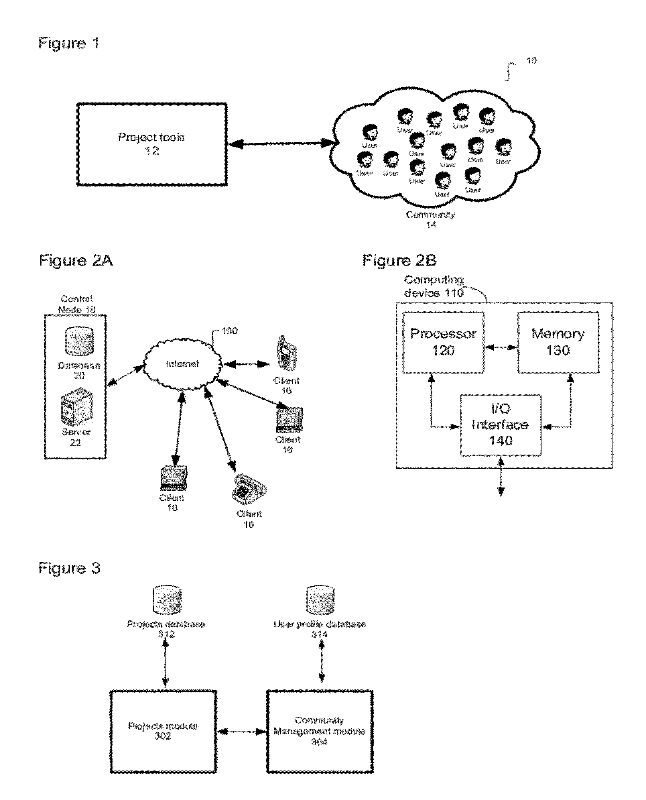
[0036]FIG. 1 shows a collaboration system 10 that includes two main components, namely a suite of building project tools 12 and a community of users 14 that is functionally linked to the suite of project tools 12.

[0037]FIG. 2A shows one possible non-limiting form of implementation of the collaboration system 10. The system 10 that is represented in this figure includes clients 16, a central node 18 and a network 100 that serves to interconnect the clients 16 and the node 18. Although four clients 16 are illustrated in FIG. 2A, it should be understood that any number of clients 16 could be included within the system 10.

[0038]Each of the clients 16 may be in the form of a computing device 110, of which an example is provided in FIG. 2B. The computing device 110 may be equipped with a processor 120, a memory 130 and an input / output (I / O) interface 140. The aforementioned components of each computing device 110 may be connected via an interconnection system such as copper or optical con...


PUM


Abstract

A method for enabling collaboration between individuals to design, construct and maintain a building. The method comprises providing a network based computer system including at least one server and multiple clients. The multiple clients allow respective individuals to interact with the server. The server includes a machine-readable storage, which is encoded with software for execution by a CPU for allowing individuals at the respective clients to create, execute and manage projects associated with at least one of a design phase, construction phase and maintenance phase of the building. Each project comprises one or more events that are related to time. The method also comprises storing in the machine-readable storage events as they occur during execution of each project to create a building project database spanning at least the design phase and the construction phase and optionally the maintenance phase of the building.

Description

CROSS REFERENCE TO RELATED APPLICATIONS[0001]This application claims the benefit under 35 USC §119(e) of U.S. provisional patent application Ser. No. 61 / 329,890 filed Apr. 30, 2010. The contents of the above-mentioned patent application are incorporated herein by reference.FIELD OF THE INVENTION[0002]The invention generally relates to a network based collaboration tool used to enable communication and collaboration between people working on industrial, commercial or residential construction projects.BACKGROUND OF THE INVENTION[0003]Residential, commercial and industrial construction and building projects can involve many different people and organizations, such as architects, contractors, electricians, accountancy firms, plumbers, painters, and material supply firms, among others. Although each person or group of people may not be known to each other beforehand, they may all collaborate at some time in order to design, construct and maintain the intended building.[0004]Unfortunately...

Claims


Application Information

Patent Timeline
Patent Type & Authority Applications(United States)
IPC IPC(8): G06F15/16
CPCG06F17/5004G06F2217/04G06Q20/123G06Q10/067G06Q10/103G06Q10/101G06F16/95G06F2111/02G06F30/13
Inventor CULVER, ANDREWTUCKER, KARENGAGLIARDI, JEANRYBAKOV, SERGEI
Owner ILIV TECH
Why Eureka
Try Eureka