
Blanking Punch

Active Publication Date: 2019-12-19
BAYERISCHE MOTOREN WERKE AG
View PDF0 Cites 1 Cited by
  • Summary
  • Abstract
  • Description
  • Claims
  • Application Information

AI Technical Summary

Benefits of technology

[0033]Expediently, as a result of the geometry or the cooperation of the blanking punch with the extraction tool, the removal of the blanking punch is thus effected counter to the blanking direction. It is particularly advantageous here that, as a result of the use of the extraction tool or of the cooperation of the arranging portion thereof with the engaging portion of the blanking punch, a force is generated that acts exactly or substantially exactly along the lo

Problems solved by technology

These make it harder to use known blanking tools, since very high forces are required in order to withdraw the blanking punch again after blanking.
It is particularly multilayer metal sheets that are problematic here, in particular when different materials are used, for example aluminum and steel, since the different layers have different flow properties.
Although blanking tools are also known that are quite capable of p

Method used


Image

  • Blanking Punch
  • Blanking Punch

Examples


Example

DETAILED DESCRIPTION OF THE DRAWINGS

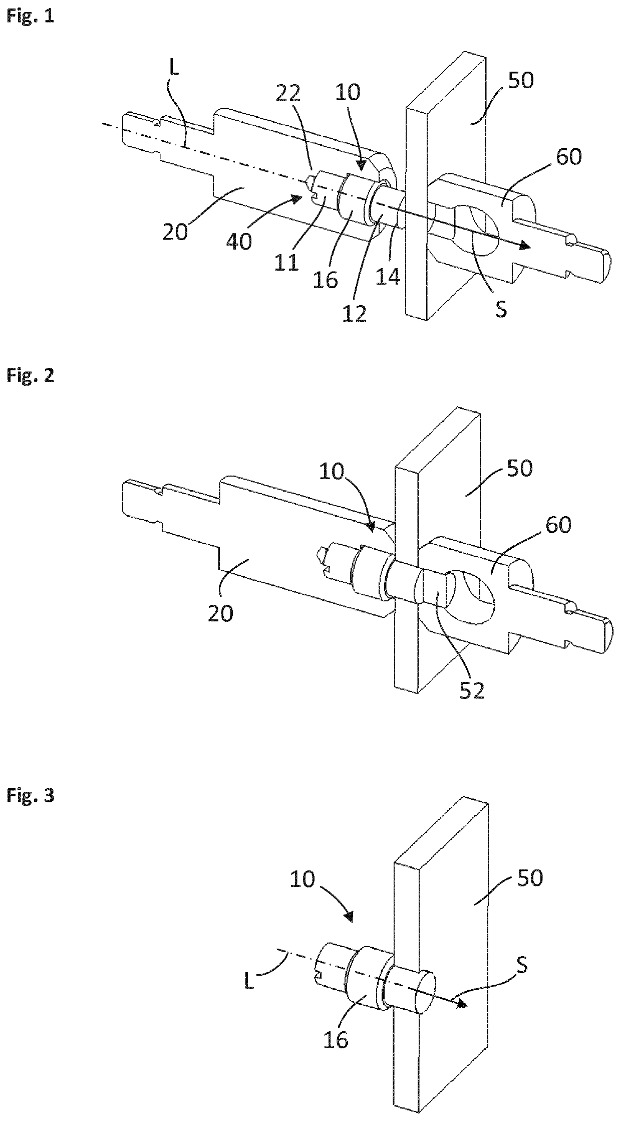
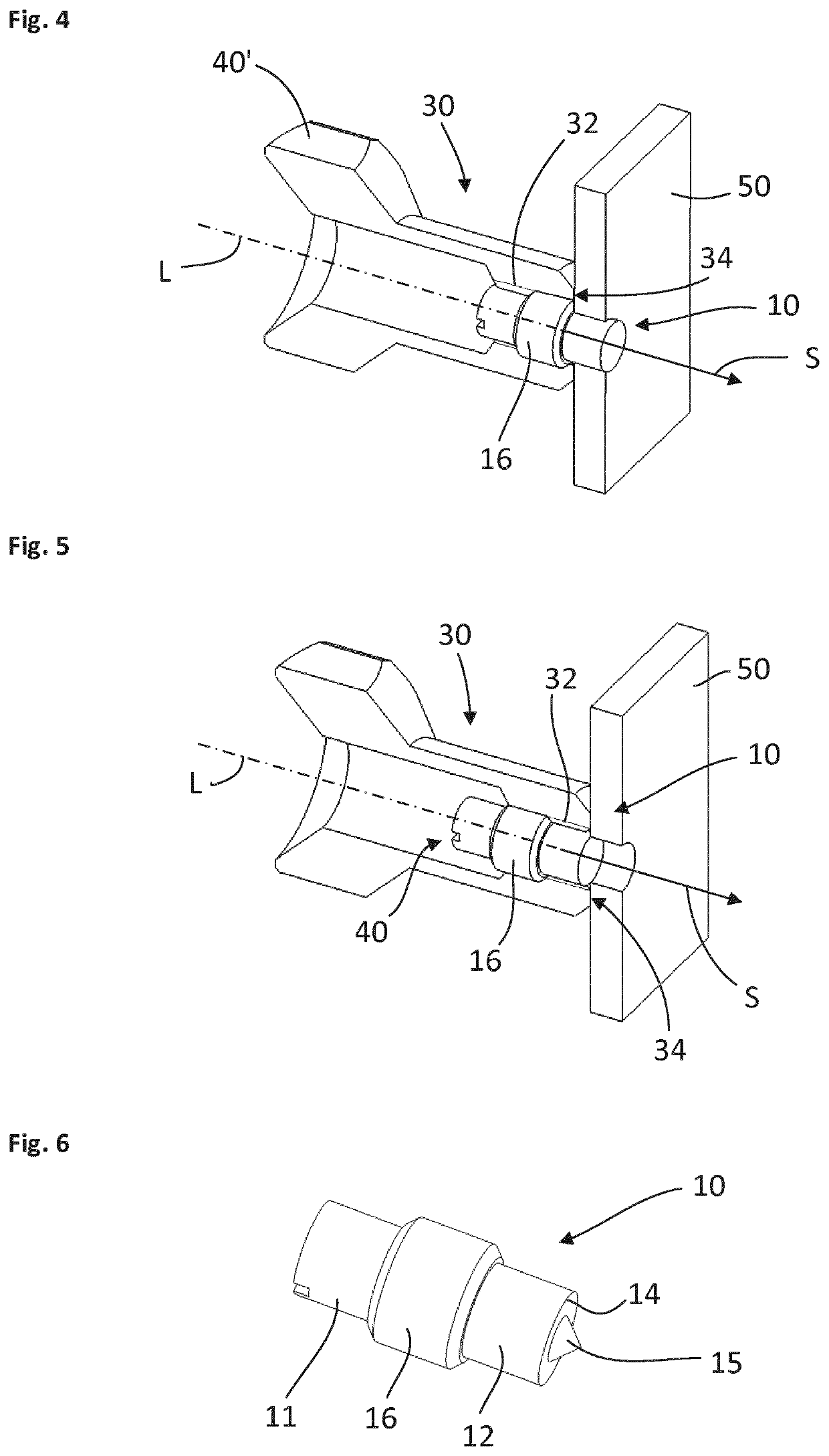
[0043]FIG. 1 shows a perspective illustration, illustrated partially in section, of a blanking mandrel including a punch receptacle 20, in which a blanking punch 10 is arranged. The entire arrangement extends along a longitudinal axis L, wherein the reference sign S and the corresponding arrow indicate a blanking direction. The blanking mandrel is arranged on a workpiece 50, for example on a (multilayer) metal sheet, wherein, on the opposite side from the blanking mandrel, a die 60 bears against the workpiece or metal sheet 50. The blanking punch 10 includes a first portion 11 and a second portion 12, wherein an engaging portion 16 is arranged in between. According to a preferred embodiment, the latter has an external thread or is formed as a thread, although this is not shown in the illustration sketched here for reasons of clarity. The second portion 12 includes a round, in particular circular, cutting edge 14, while the first portion 11 has an ...


PUM

PropertyMeasurementUnit
Diameteraaaaaaaaaa

Abstract

A blanking punch which extends from a first portion to a second portion along a blanking direction is provided. The second portion has a cutting edge. An engaging portion is provided/designed between the first portion and the second portion. The engaging portion enables the blanking punch to be removed from a workpiece counter to the blanking direction.

Description

CROSS REFERENCE TO RELATED APPLICATIONS[0001]This application is a continuation of PCT International Application No. PCT / EP2018 / 050651, filed Jan. 11, 2018, which claims priority under 35 U.S.C. § 119 from German Patent Application No. 10 2017 203 231.6, filed Feb. 28, 2017, the entire disclosures of which are herein expressly incorporated by reference.BACKGROUND AND SUMMARY OF THE INVENTION[0002]The present invention relates to a blanking punch, a blanking mandrel, a blanking tool, a blanking set, and a method for blanking.[0003]In body and vehicle construction, use is increasingly being made of high-strength metal sheets, in particular including multilayer high-strength metal sheets. These make it harder to use known blanking tools, since very high forces are required in order to withdraw the blanking punch again after blanking. It is particularly multilayer metal sheets that are problematic here, in particular when different materials are used, for example aluminum and steel, sin...

Claims


Application Information

Patent Timeline
IPC IPC(8): B21D28/34B21D35/00B21D45/00
CPCB21D35/007B21D28/34B21D45/003
Inventor GEIGER, MICHAELSUTTER, NATHANAEL
Owner BAYERISCHE MOTOREN WERKE AG
Learn More