
Arrangement for supporting a circuit board

Inactive Publication Date: 2002-03-26
DIEHL STIFTUNG
View PDF11 Cites 3 Cited by
  • Summary
  • Abstract
  • Description
  • Claims
  • Application Information

AI Technical Summary

Benefits of technology

The elastic damping layer provided between the circuit board and the metal carrier plate, and in particular the metal carrier plate itself, serve to carry the axial force components of the acceleration forces. In accordance with the invention the operational reliability of the circuit board is improved in comparison with known arrangements of the general kind set forth, in that it comprises a carbon fibre-reinforced plastic material.
In order to eliminate radial force components not just by virtue of the provision in the metal carrier plate of a through hole which is preferably provided in a central region of the metal carrier plate, it is desirable if the circuit board and the damping layer are also formed with holes. The last-mentioned holes can be in overlapping relationship with the through hole in the metal carrier plate. In that respect, the holes in the circuit board and in the damping layer and the through hole in the metal carrier plate can be at least approximately coincident with each other. Such a configuration of the above-described kind reliably eliminates radial force components resulting from the extremely high acceleration force of a projectile or missile so that damage to the circuit board or the functional components provided thereon can be reliably excluded.
Desirably the metal carrier plate is screwed to the above-mentioned projecting mounting portion in the axial direction of the projectile. That affords the advantage of ease of assembly.

Problems solved by technology

A disadvantage with the operation of embedding the circuit into the block by foaming is that the mobility of functional components which must be movable can be adversely affected.
Another detrimental aspect is that, when the material foams up, mechanical stresses can occur between the functional components and the circuit board, and such stresses can possibly result in the electrical connection between the functional components and the circuit board being torn away.
Similar disadvantages occur if the circuit board and the functional parts or components are cast or moulded into a block.
That known support arrangement involves force components in a radial direction, and that, having regard to the extremely high acceleration forces which occur in the case of a projectile, can give rise to major problems in regard to operational reliability of the circuit board or the functional components provided thereon.

Method used


Image

  • Arrangement for supporting a circuit board
  • Arrangement for supporting a circuit board

Examples


Embodiment Construction

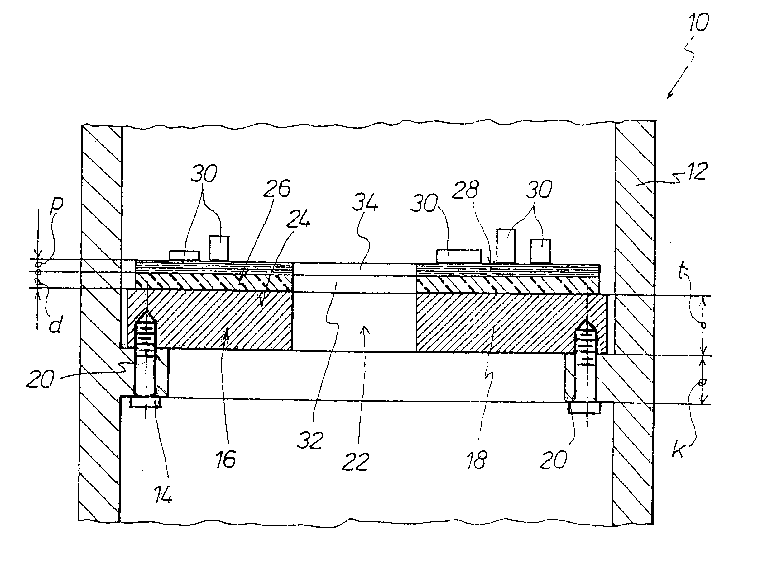
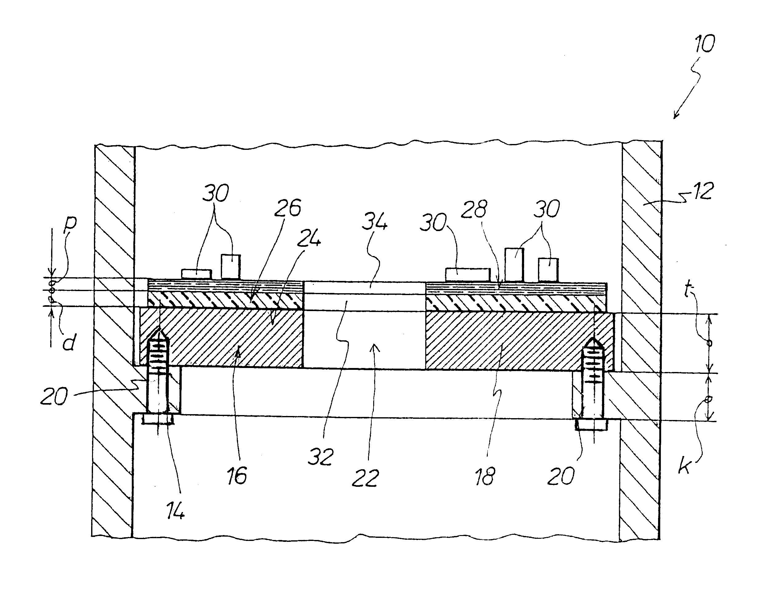
The FIGURE is a view in longitudinal section of a portion of a projectile or missile 10, from the wall 12 of which a peripherally extending protruding mounting portion 14 projects integrally radially inwardly. Screwed fast to the projecting mounting portion 14 is a carrier 16 which is formed by a metal plate 18. The screwing of the metal carrier plate 18 to the projecting mounting portion 14 which extends in the peripheral direction in the interior of the projectile 10 is diagrammatically indicated by thin dash-dotted lines 20 representing the centre lines of suitable screws.

The metal carrier plate 18 is provided with a through hole 22 in a central region.

An elastic damping layer 26 is provided on the main surface 24 of the metal carrier plate 18, which main surface faces away from the projecting mounting portion 14. Arranged on the damping layer 26 is a circuit board 28 having electrical or electronic functional components 30. The damping layer 26 preferably comprises a cellular po...


PUM


Abstract

Described is an arrangement for supporting a circuit board (28) having functional components (30) on a carrier (16) of a projectile (10). The carrier (16) has a metal plate (18). The circuit board (28) comprises a carbon fibre-reinforced plastic material. Provided between the circuit board (28) and the metal carrier plate (18) is an elastic damping layer (26). The circuit board (28) and the damping layer (26)-like the metal carrier plate (18)-are spaced with their peripheral edges from the inside wall of the housing of the projectile (10).

Description

1. Field of the InventionThe invention concerns an arrangement for supporting a circuit board having functional components which are located on a carrier on a projectile.2. Discussion of the Prior ArtDE 34 01 513 C2 discloses a projectile or missile in which an electronic firing circuit is disposed in a fuse housing which is fixed to the projectile casing. In that arrangement the firing circuit is foamed into a plastic material hard foam block. Fitted into the fuse housing are flat elastic damping bodies which jointly enclose the hard foam block on all sides.A disadvantage with the operation of embedding the circuit into the block by foaming is that the mobility of functional components which must be movable can be adversely affected. Another detrimental aspect is that, when the material foams up, mechanical stresses can occur between the functional components and the circuit board, and such stresses can possibly result in the electrical connection between the functional components ...

Claims


Application Information

Patent Timeline
IPC IPC(8): F42C19/00F42C19/02H05K7/14H05K3/00H05K1/02
CPCF42C19/02H05K1/0271H05K7/1461H05K3/0061H05K2201/2045H05K2201/0133
Inventor FURST, WILHELMKRATZ, BERNHARD
Owner DIEHL STIFTUNG
Learn More