Developing apparatus and image forming apparatus

a technology of developing apparatus and image forming apparatus, which is applied in the direction of electrographic process apparatus, instruments, corona discharge, etc., can solve the problems of reducing the affecting the quality of toner, etc., to achieve the effect of suppressing restriction failure, suppressing toner deterioration, and maintaining the necessary charge amount of toner

Active Publication Date: 2019-12-19
CANON KK
View PDF12 Cites 0 Cited by
  • Summary
  • Abstract
  • Description
  • Claims
  • Application Information

AI Technical Summary

Benefits of technology

[0006]Thus, a developing apparatus capable of maintaining toner charge amount necessary for high-quality image formation and capable of suppressing a restriction failure caused by sticking of toner to a developing roller surface and suppressing toner deterioration has been sought after.

Problems solved by technology

However, in the configuration in which the fur brush or the sponge roller is brought into contact with the developing roller to strip the toner, the stripping member mechanically rubs the toner, and hence there is a problem in that physical properties of toner may change due to a separated or buried external additive (hereinafter referred to as “toner deterioration”).
When this problem occurs, the charge amount of toner decreases, and a problem of so-called fogging or density decrease occurs.
However, in such a configuration, when time has elapsed from the previous image formation in the state in which toner becomes clogged near a contact nip between the moving member and the developing roller, a history thereof becomes image density unevenness, which causes another problem.

Method used


Image

  • Developing apparatus and image forming apparatus
  • Developing apparatus and image forming apparatus
  • Developing apparatus and image forming apparatus

Examples


first embodiment

[0037]In the first embodiment, modes for embodying the invention are described in the following order:[0038]1. Outline of image forming apparatus;[0039]2. Outline of developing apparatus including moving member; and[0040]3. Description of operation sequence of developing roller and brush roller.

[0041]Outline of Image Forming Apparatus

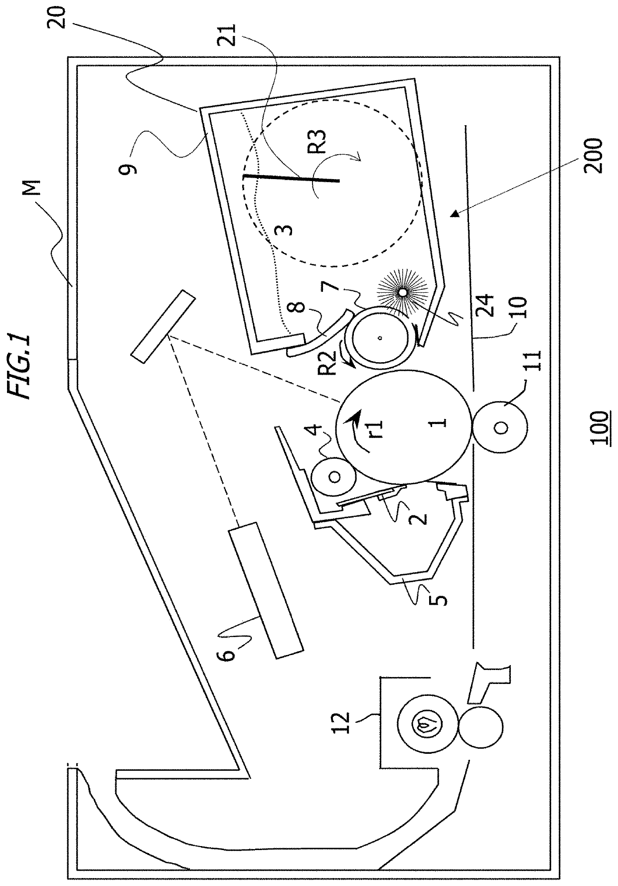
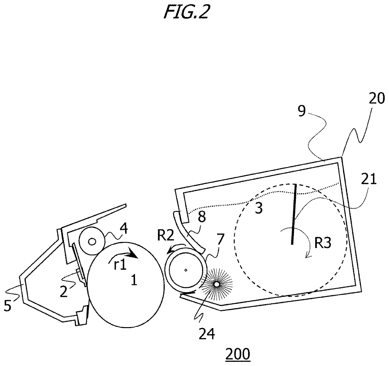
[0042]FIG. 1 illustrates a cross-sectional view of an image forming apparatus 100 according to the first embodiment. In a main body M of the image forming apparatus 100, a photosensitive drum 1 serving as an image bearing member is provided as a member to be charged. The photosensitive drum 1 is obtained by forming an organic photosemiconductor (OPC) photosensitive layer on the outer peripheral surface of a conductive drum, and when a driving command is transmitted from the main body, the photosensitive drum 1 is rotationally driven in a direction denoted by r1 in the figures at predetermined process speed of 188 mm / sec. The surface of the photosensitiv...

second embodiment

[0124]Next, the second embodiment is described. The second embodiment is different from the first embodiment in the operation sequence of the developing roller 7 and the brush roller 24, but is the same as the first embodiment in other points. Thus, descriptions overlapping with the first embodiment are omitted below.

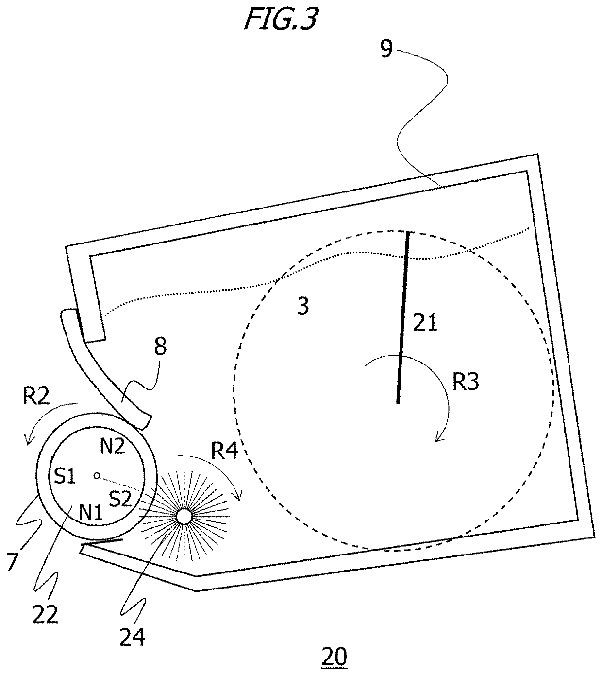
[0125]FIG. 18A and FIG. 18B are schematic diagrams related to surface moving speed vectors of the developing roller 7 and the brush roller 24 according to the second embodiment. In FIG. 18A and FIG. 18B, the rotation direction of the developing roller 7 during image forming processing is counterclockwise, and the rotation direction of the brush roller 24 is clockwise. Thus, speed vectors R and r are directed in the same direction, and at a point T, the speed of the developing roller 7 is larger than the speed of the brush roller 24, so that |R|>|r| is established. In the second embodiment, as an example, the speed |R| of the developing roller 7 is 188 mm / sec, and the sp...


PUM


Abstract

A developing apparatus, includes: a developer bearing member that is rotatable; an moving member configured to move the magnetic developer carried on the developer bearing member before the magnetic developer is restricted by a restricting member, the moving member being rotatable and brought into contact with a surface of the developer bearing member; and a control portion, wherein, at a contact position between the developer bearing member and the moving member, assuming that a moving speed vector of a surface of the developer bearing member is taken as R and a moving speed vector of a surface of the moving member is taken as r, the control portion controls rotational operation of the developer bearing member and the moving member such that a direction of a vector R−r during image formation and a direction of a vector R−r during non-image formation be opposite to each other.

Description

BACKGROUND OF THE INVENTIONField of the Invention[0001]The present invention relates to a developing apparatus for developing an electrostatic latent image formed on a photosensitive drum, and an image forming apparatus for forming an image on a recording medium by using a developer.Description of the Related Art[0002]Conventionally, an electrophotographic image forming apparatus using a magnetic single-component developing configuration develops toner on an electrostatic latent image by using magnetic toner, a developing roller for bearing the magnetic toner, a fixed magnet disposed in the developing roller, and a developing blade for restricting the magnetic toner on the surface of the developing roller to a predetermined toner layer. The magnetic toner on the surface of the developing roller is present in the form of chains (the magnetic toner is hereinafter referred to as “magnetic chains”) by a magnetic field of the fixed magnet. The magnetic chains are frictionally charged whe...

Claims


Application Information

Patent Timeline
Patent Type & Authority Applications(United States)
IPC IPC(8): G03G15/08G03G15/09G03G15/02
CPCG03G15/0921G03G15/0812G03G15/0216G03G15/0808G03G15/09G03G2215/0609
Inventor KATO, MASAHITOFUJINO, HIROKAZUFUKUSHIMA, NAOKITODA, ATSUSHIBABA, DAISUKEKISHI, YOSUKEHIROSE, MASAKI
Owner CANON KK
Why Eureka
Try Eureka