Detecting device for piston rod bounce value

A detection device and piston rod technology, applied in the direction of measuring devices, instruments, etc., can solve problems such as unfavorable, little reference significance for compressor performance changes, unfavorable scientific management of compressors, etc., and achieve the effect of accurate monitoring and measurement

Inactive Publication Date: 2018-12-07
CHENGDU TIANYI NATURAL GAS COMPRESSOR MFG
View PDF6 Cites 0 Cited by
  • Summary
  • Abstract
  • Description
  • Claims
  • Application Information

AI Technical Summary

Problems solved by technology

[0007] In order to achieve the above-mentioned solution to the existing means of measuring the piston rod runout value, which only reflects the piston rod runout value of the compressor at a certain moment, which has little reference significance for the performance change of the compressor, and is not conducive to the scientific management of the compressor, the present invention provides the following Technical solution: The detection device for the runout value of the piston rod, including the stuffing box assembly, the compressor control system, the cover plate of the middle body, the measuring installation bracket, the middle body of the compressor, the level measuring instrument, the vertical measuring instrument, the first data transmission cable, The second data transmission cable, the compressor control system includes an A / D analog input module, the inside of the 
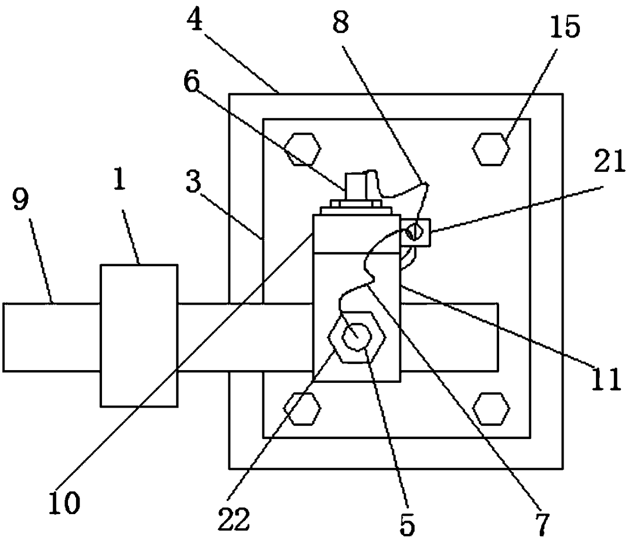
stuffing box assembly is equipped with a piston rod, and the measurement installation bracket includes a horizontal plate, the two ends of the bottom of the horizontal plate A first fixed plate and a second fixed plate are fixedly connected respectively, a first through hole is opened on the vertical side wall of the first fixed plate, and a first hex nut is fixedly connected inside the first through hole, The outer wall of the level measuring instrument is provided with a first thread, and the level measuring instrument is threadedly connected with the first hex nut, and one end of the level measuring instrument extends to one side of the piston rod, and the level measuring instrument The other end is fixedly connected to the first data transmission cable, and a second through hole is provided on the horizontal plate, and a second hex nut is fixedly connected to the inside of the second through hole, and on the outer wall of the vertical measuring instrument A second thread is provided, and the vertical measuring instrument is threadedly connected with the second hex nut, one end of the vertical measuring instrument extends to one side of the piston rod, and the other end of the vertical measuring instrument is connected to the second data The 
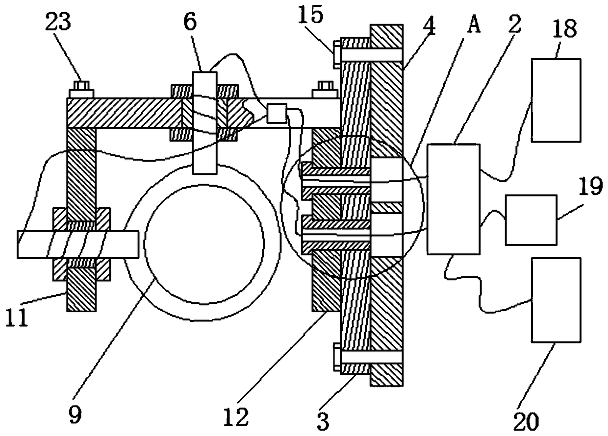
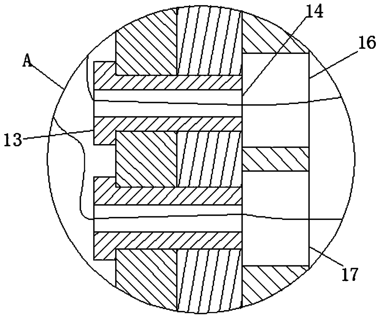
transmission cable is fixedly connected, two symmetrical first threaded through holes are opened on the vertical side wall of the second fixing plate, and two second threaded through holes are opened on the vertical side wall of the middle cover plate. holes, the two first threaded through holes correspond to the two second threaded through holes respectively, the insides of the first threaded through holes and the second threaded through holes are jointly threaded with first bolts, and the second threaded through holes The fixed plate and the middle body cover are fixedly connected by first bolts, the two first bolts are provided with third through holes, and the four corners of the vertical side walls of the middle body cover are provided with third threaded holes. The vertical side wall of the middle body of the compressor is provided with four fourth threaded through holes, the four fourth threaded through holes correspond to the four third threaded through holes respectively, and the third threaded through holes The inside of the through hole and the fourth threaded through hole are commonly threaded to be connected with a second bolt, and the cover plate of the middle body is fixedly connected with the middle body of the compressor through the second bolt, and the vertical side wall of the middle body of the compressor is provided with a The fourth through hole and the fifth through hole, the fourth through hole and the fifth through hole respectively correspond to the two second threaded through holes, and the end of the first data transmission cable away from the level measuring instrument passes through it sequentially A third through hole and a fifth through hole are connected with the compressor control system, and the end of the second data transmission cable away from the vertical measuring instrument passes through another third through hole and the fourth through hole in turn and is connected with the compressor The compressor control system is connected with a touch screen through the first data line, the compressor control system is connected with an alarm through the second data line, and the compressor control system is connected through the third data line line connected with timer

Method used


Image

  • Detecting device for piston rod bounce value
  • Detecting device for piston rod bounce value
  • Detecting device for piston rod bounce value

Examples


Embodiment Construction

[0023] The following will clearly and completely describe the technical solutions in the embodiments of the present invention with reference to the accompanying drawings in the embodiments of the present invention. Obviously, the described embodiments are only some, not all, embodiments of the present invention. Based on the embodiments of the present invention, all other embodiments obtained by persons of ordinary skill in the art without making creative efforts belong to the protection scope of the present invention.

[0024] see Figure 1-4 , the detection device for the beating value of the piston rod, including the stuffing box assembly 1, the compressor control system 2, the middle body cover plate 3, the measuring installation bracket, the compressor middle body 4, the horizontal measuring instrument 5, the vertical measuring instrument 6, the first The data transmission cable 7, the second data transmission cable 8, the compressor control system 2 includes an A / D analo...


PUM


Abstract

The invention relates to the technical field of compressor working condition detection, and discloses a detecting device for a piston rod bounce value, which comprises a packing box assembly, a compressor control system, a middle body cover plate, a measurement mounting bracket, a compressor middle body, a horizontal measuring instrument, a vertical measuring instrument, a first data transmissioncable, and a second data transmission cable. The compressor control system includes an A/D analog input module, a piston rod is mounted inside the packing box assembly, and the measurement mounting bracket includes a horizontal plate. The detecting device for the piston rod bounce value can monitor the bounce of the piston rod of the compressor at all times, so as to obtain the bounce value of thepiston rod in the whole process of the compressor operation, and timely reflect the change of the working condition of the piston rod of the compressor. The compressor is enabled to stop or work normally for different operating conditions of the compressor piston rod, which is beneficial to monitor the performance of the compressor and reduce and control the compressor equipment failure.

Description

technical field [0001] The invention relates to the technical field of compressor working condition detection, in particular to a detection device for the jumping value of a piston rod. Background technique [0002] The natural gas compressor is a continuous working device, and its service life is determined by the balance stability and tightness of the seal. The beating of the piston rod in the compressor is the primary factor that determines the sealing performance of the compressor. Therefore, it is particularly important to detect the jumping of the piston rod in motion, which is also one of the measures to improve the performance of the compressor. [0003] The existing detection method for the jumping value of the piston rod is generally as follows: when the compressor is running, remove the middle body cover plate of the compressor, install the dial indicator on the frame close to the compressor stuffing box assembly, and the dial indicator The measuring head is pla...

Claims


Application Information

Patent Timeline
Patent Type & Authority Applications(China)
IPC IPC(8): G01B21/00
CPCG01B21/00
Inventor 余世春
Owner CHENGDU TIANYI NATURAL GAS COMPRESSOR MFG
Why Eureka
Try Eureka