Liquid ejecting apparatus

a liquid ejecting apparatus and liquid ejector technology, which is applied in the direction of power drive mechanisms, printing mechanisms, printing, etc., can solve the problems of failure of blowing machines, and errors in the landing position of discharged liquid droplets, so as to suppress the adherence of scattering mist

Active Publication Date: 2013-04-30
SEIKO EPSON CORP
View PDF7 Cites 0 Cited by
  • Summary
  • Abstract
  • Description
  • Claims
  • Application Information

AI Technical Summary

Benefits of technology

[0008]An advantage of some aspects of the invention is that it provides a liquid ejecting apparatus capable of controlling failures caused by discharged liquid droplets while maintaining the discharge stability of the liquid droplets.
[0010]According to the structure, the liquid ejecting apparatus includes a liquid ejecting head which ejects liquid from a nozzle orifice, a blowing mechanism disposed on the liquid ejecting head side, and a gap control unit which relatively controls a gap between the nozzle orifices and an ejection target medium, in which the driving of the blowing mechanism is controlled depending on the gap between the nozzle orifices and the ejection medium. Accordingly, when the gap between the nozzle orifices and the ejection target medium is narrow, the blowing mechanism is driven to blow a stream of air, which can suppress the air volatilizing from the liquid droplets landing on the ejection target medium from adhering to a recording head. On the other hand, when the gap between the nozzle orifices and the ejection target medium is wide, the driving of the blowing mechanism is weakened so that the stream of air becomes weak. As a result, the liquid droplets can land on predetermined landing positions and it is possible to suppress the scattering of satellite droplets incidentally produced around the discharged liquid droplets in the form of mist in the device due to the stream of air blown from the blowing mechanism. Therefore, it is possible to suppress the occurrence of a device failure such as an electrical short-circuit of an electronic part such as a circuit board which is attributable to adherence of volatilizing liquid droplets and scattering mist and suppress the deterioration of an adhesive used in the liquid ejecting head regardless of the gap between the nozzle orifices and the ejection target medium while maintaining the discharge stability of the liquid droplets.
[0012]According to the structure, the gap between the nozzle orifices and the ejection target medium is controlled in at least two steps and the driving mechanism is more weakly driven as the gap between the nozzle orifices and the ejection target medium becomes wider. Accordingly, it is possible to suppress the adherence of the air volatilizing from the liquid droplets and the scattering mist to the liquid ejecting head while maintaining the discharge stability of the liquid droplets.
[0014]According to the structure, when the gap between the nozzle orifices and the ejection target medium is a predetermined size or larger, the driving of the blowing mechanism is stopped. Accordingly, it is possible to prevent the scattering of mist which accompanies the blowing of the stream of air from the blowing mechanism.
[0016]According to the structure, the blowing mechanism has a cover surrounding the blowing mechanism and having an opening on the ejection target medium side, in which when the gap between the nozzle orifices and the ejection target medium is a predetermined size or larger, the opening of the cover is closed by a cover member. Accordingly, it is possible to suppress the adherence of the scattering mist to the inside of the blowing mechanism.

Problems solved by technology

The liquid droplets, which turned into mist, (hereinafter, referred to as mist of liquid droplets) cause problems such that they pollute the inside of the device by scattering in the air while they are flying and cause a failure such as an electrical short-circuit by sticking to an electronic part such as a circuit board.
As a result, there is a possibility that an adhesive used in the liquid ejecting head is likely to deteriorate.
However, in the technique, if the stream of air is blown from the blowing machine in the case in which a platen gap (gap between the nozzle orifices and the recording medium) is large, the mist of the liquid droplets is easily scattered in the device, which causes failures of the blowing machine and errors in the landing position of the discharged liquid droplets.
On the other hand, when the gap between the nozzle orifices and the ejection target medium is wide, the driving of the blowing mechanism is weakened so that the stream of air becomes weak.

Method used


Image

  • Liquid ejecting apparatus
  • Liquid ejecting apparatus
  • Liquid ejecting apparatus

Examples


Embodiment Construction

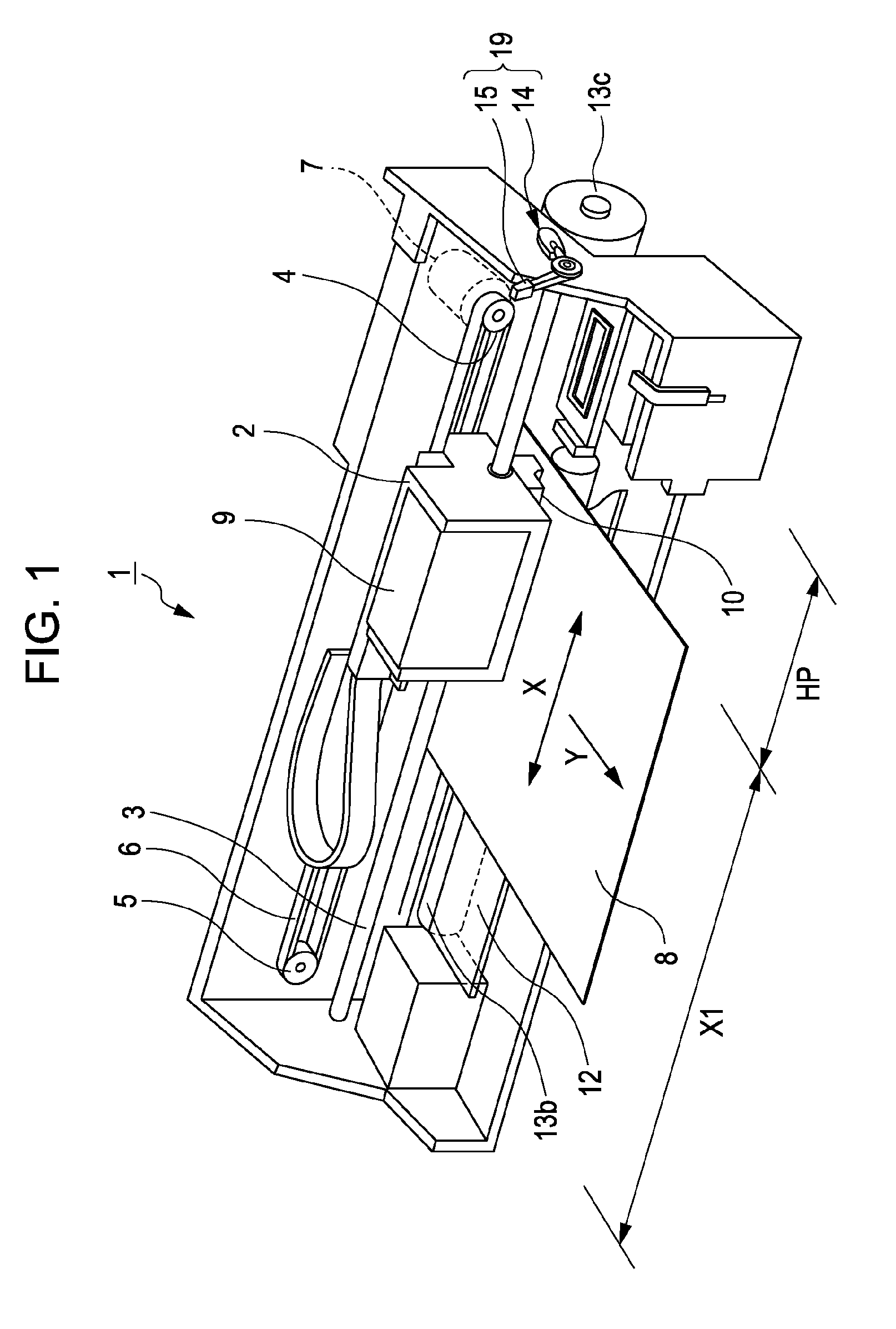
[0024]Hereinafter embodiments of the invention will be described with reference to the accompanying drawings. FIG. 1 is a perspective view illustrating an ink jet printer which is a representative ink jet type recording device. First, the entire structure will be described with reference to FIG. 1.

[0025]An ink jet printer 1 is structured such that a carriage 2 is movably attached to a guide shaft 3 and the carriage 2 is connected to a timing belt 6 stretched across a gap between a drive pulley 4 and a freely rotating pulley 5. The drive pulley 4 is united with a rotary shaft of a pulse motor 7 and the carriage 2 is moved in a widthwise direction (main scanning direction, denoted by a reference X in the figure) of recording paper (an ejection target medium) 8 when the pulse motor 7 is driven. An ink cartridge 9 is detachably attached to an upper portion of the carriage 2, and a pair of recording heads 10 is attached to the surface (lower surface) of the carriage 2 which faces the rec...


PUM


Abstract

A liquid ejecting apparatus includes a liquid ejecting head which ejects liquid from a nozzle orifice, a blowing mechanism disposed on the liquid ejecting head side, and a gap control unit which relatively controls a gap between the nozzle orifices and an ejection target medium, in which driving of the blowing mechanism is controlled depending on the gap between the nozzle orifices and the ejection target medium.

Description

BACKGROUND[0001]1. Technical Field[0002]The present invention relates to a liquid ejecting apparatus which discharges liquid from nozzle orifices of a liquid ejecting head such as an ink jet recording head.[0003]2. Related Art[0004]There are several types of liquid ejecting heads which discharge (or eject) liquid droplets from nozzle orifices by causing liquid pressure to change in a pressure chamber. Examples of such liquid ejecting heads include an ink jet recording head (hereinafter, simply referred to as recording head) used in an image recording device such as an ink jet recording device (hereinafter, simply referred to as printer), a color material ejecting head used to manufacture a color filter of a liquid crystal display, an electrode material ejecting head used to form an electrode of an organic electro luminescence (EL) display or a field emission display (FED), and a bioorganic substance ejecting head used to manufacture a biochip (biochemical element).[0005]In the recor...

Claims


Application Information

Patent Timeline
Patent Type & Authority Patents(United States)
IPC IPC(8): B41J25/308B41J2/165
CPCB41J2/1714B41J25/3082
Inventor TOGAWA, YUKI
Owner SEIKO EPSON CORP
Why Eureka
Try Eureka