Coil component
- Summary
- Abstract
- Description
- Claims
- Application Information
AI Technical Summary
Benefits of technology
Problems solved by technology
Method used
Image
Examples
first embodiment
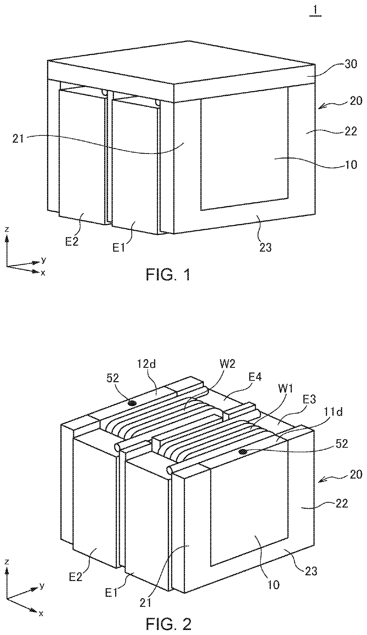
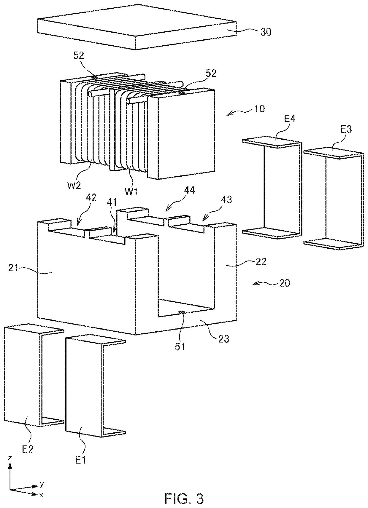
[0053]FIG. 1 is a schematic perspective view illustrating the outer appearance of a coil component 1 according to the present invention. FIG. 2 is a schematic perspective view illustrating a state where a plate-like magnetic core 30 is removed from the coil component 1, and FIG. 3 is a schematic exploded perspective view of the coil component 1.
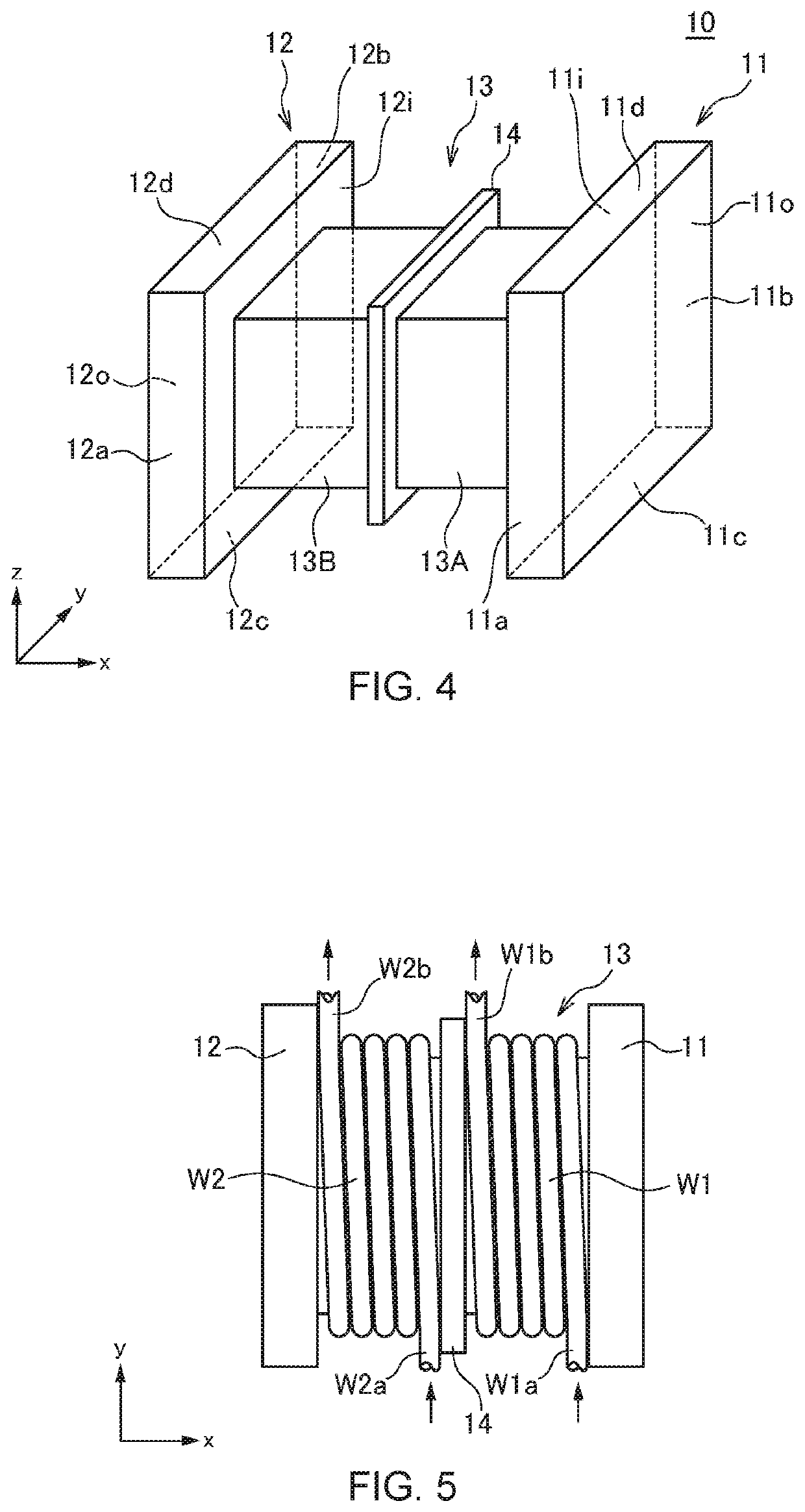
[0054]The coil component 1 according to the present embodiment is a coil component suitably used as a common mode filter for power supply or a coupling inductor and includes, as illustrated in FIGS. 1 to 3, a drum-shaped first magnetic core 10, a C-shaped second magnetic core 20 covering the first magnetic core 10 from three directions, a plate-like third magnetic core 30 covering the first magnetic core 10 from one direction, and a pair of wires W1 and W2.
[0055]The drum-shaped first magnetic core 10 is wound with the pair of wires W1 and W2 such that the coil axis direction is the x-direction. One ends of the wires W1 and W2 are connected to...
second embodiment
[0086]FIG. 20 is a schematic exploded perspective view for explaining the structure of a coil component 2 according to the present invention.
[0087]As illustrated in FIG. 20, the coil component 2 according to the second embodiment differs from the coil component 1 according to the first embodiment in that flat-type wires W1 and W2 each having a flat shape in cross section are used, and that the terminal electrodes E1 to E4 are omitted. Other configurations are the same as those of the coil component 1 according to the first embodiment, so the same reference numerals are given to the same elements, and overlapping description will be omitted.
[0088]In the present embodiment, the end portions of the flat-type wires W1 and W2 are bent, and the bent portions are used as the terminal electrodes as they are. That is, one ends of the wires W1 and W2 extend in the z-direction along the first wall surface part 21 of the second magnetic core 20 and then bent in the y-direction along the third w...
third embodiment
[0092]FIG. 25 is a schematic perspective view illustrating the outer appearance of a coil component 3 according to the present invention.
[0093]As illustrated in FIG. 25, the coil component 3 according to the third embodiment differs from the coil component 2 according to the second embodiment in that the end portions of the flat-type wires W1 and W2 are bent to the third magnetic core 30 side. Other configurations are the same as those of the coil component 2 according to the second embodiment, so the same reference numerals are given to the same elements, and overlapping description will be omitted.
[0094]The terminal electrodes E1 to E4, which are end portions of the wires W1 and W2 are provided on the third magnetic core 30 side, and so the coil component 3 according to the present embodiment is mounted on the mounting substrate 8 in a vertically opposite direction (180 degrees) to the coil components 1 and 2 according to the first and second embodiments. As exemplified in the pre...
PUM
 Abstract
Description
Claims
Application Information
 - R&D
- Intellectual Property
- Life Sciences
- Materials
- Tech Scout
- Unparalleled Data Quality
- Higher Quality Content
- 60% Fewer Hallucinations
Browse by: Latest US Patents, China's latest patents, Technical Efficacy Thesaurus, Application Domain, Technology Topic, Popular Technical Reports.
© 2025 PatSnap. All rights reserved.Legal|Privacy policy|Modern Slavery Act Transparency Statement|Sitemap|About US| Contact US: help@patsnap.com


