
Inclination sensor

a technology of inclination sensor and inclination state, which is applied in the field of inclination sensor, can solve the problems of incorrect detection of inclination state, easy influence of external magnetic field on inclination sensor, uneven rolling of rolling elements, etc., and achieve the reduction of magnetic resistance, magnetic loss, and magnetic force detection region of hall ic.

Inactive Publication Date: 2008-08-28
ORMON CORP
View PDF1 Cites 0 Cited by
  • Summary
  • Abstract
  • Description
  • Claims
  • Application Information

AI Technical Summary

Benefits of technology

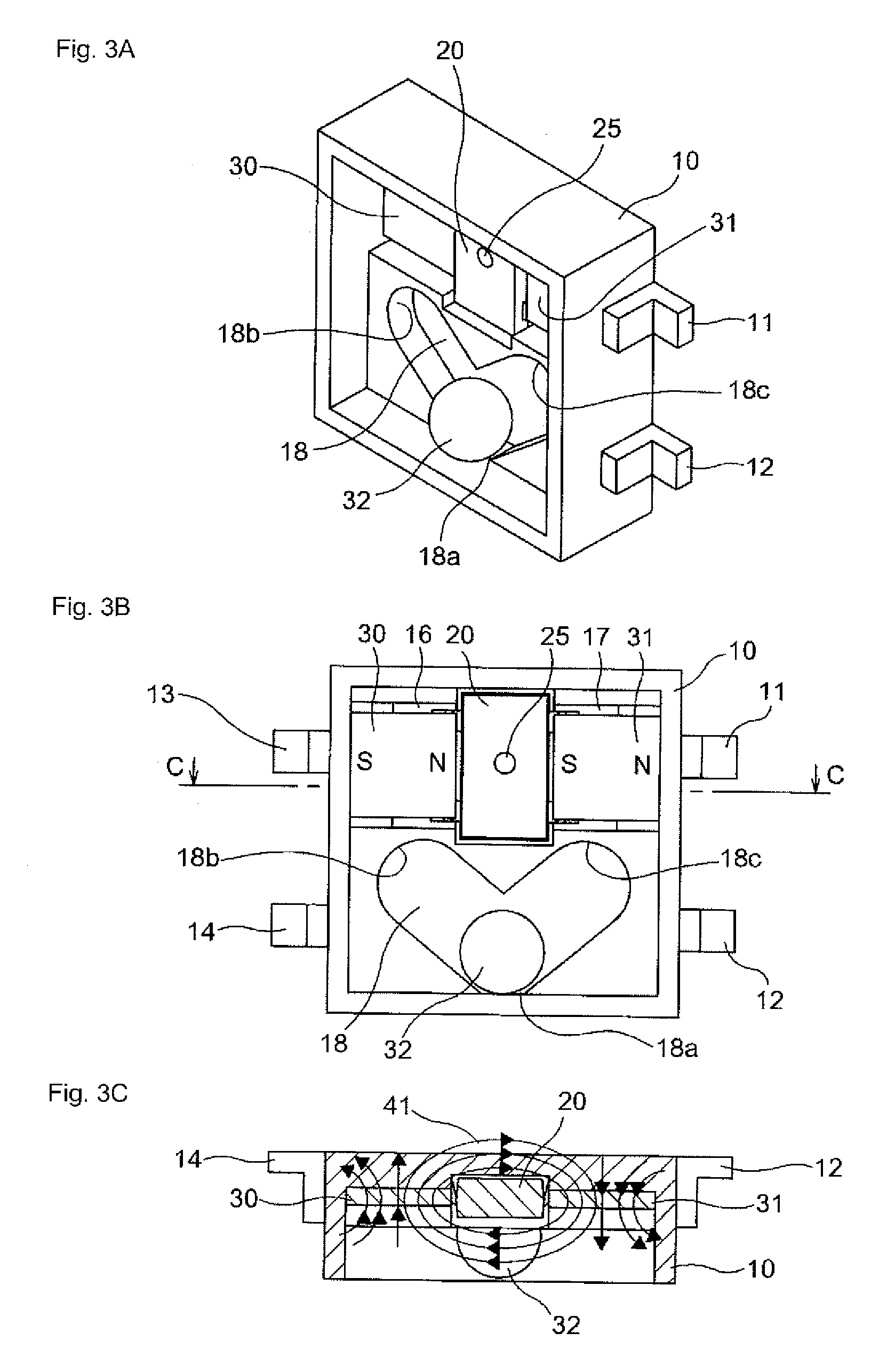
[0010]According to the invention, when the rolling element made of the magnetic material is rolled to one of the first and second end portions in the rolling groove, while a second magnetic circuit in which the magnetic line of force flows only between the rolling element and one of the pair of permanent magnets disposed adjacent to the first and second end portion is closed, the first magnetic circuit closed only between the pair of permanent magnets is eliminated. At the same time, a third magnetic circuit in which the magnetic line of force flows only between the other permanent magnet and the magnetic force detecting region of the Hall IC is closed, and the magnetic line of force of the other permanent magnet flows directly through the Hall IC. Accordingly, the space gap between the other permanent magnet and the magnetic force detecting region of the Hall IC is decreased and the magnetic resistance is decreased. Therefore, the magnetic loss is decreased and the magnetic line of force of the permanent magnet is utilized while waste is eliminated, so that the inclination sensor having the good magnetic efficiency can be obtained. Because the magnetic efficiency is improved, it is not necessary to use the large permanent magnet is not required, and it is not necessary to assemble magnetic material to the pendulum unlike the conventional technique. Therefore, according to the aspect of the invention, the compact inclination sensor having the small number of components and few assembling man-hour is obtained.
[0011]In the inclination sensor according to the aspect of the invention, preferably the rolling element is formed in a spherical shape. Accordingly, the spherical rolling element has small friction, and particularly the friction of the spherical rolling element is about one-tenth the friction generated between the pendulum and rotating shaft portion in the conventional technique. Therefore, a variation in operation characteristic caused by the friction is decreased to obtain the high-reliability inclination sensor. Unlike the conventional technique, it is not necessary that the pendulum and the magnetic material be formed by the different parts, and the small number of components and few assembling man-hour are achieved in the inclination sensor of the invention, so that the productivity can be enhanced to reduce the cost. Particularly the assembling work of the pendulum and the magnetic material, in which high assembling accuracy is required, is eliminated, so that the productivity is further improved.

Problems solved by technology

However, because the rolling element is formed by the permanent magnet in the inclination sensor, the inclination sensor is easily affected by an external magnetic field.
When an electromagnet or a magnetized metal exists around the inclination sensor, the rolling element is not smoothly rolled, and possibly the inclination state is not correctly detected.
As a result, desired magnetic efficiency is hardly obtained due to easy generation of magnetic loss and low magnetic flux density.
Accordingly, in the inclination sensor disclosed in Japanese Patent Application Laid-Open No. 2006-90796, when the magnetic line of force having the desired magnetic flux density is caused to pass through the magnetic materials, it is necessary to dispose the large permanent magnet, which results in problems of difficulty of downsizing of the apparatus, a large number of components, many assembling man-hour, and low productivity.

Method used


Image

  • Inclination sensor
  • Inclination sensor
  • Inclination sensor

Examples


Embodiment Construction

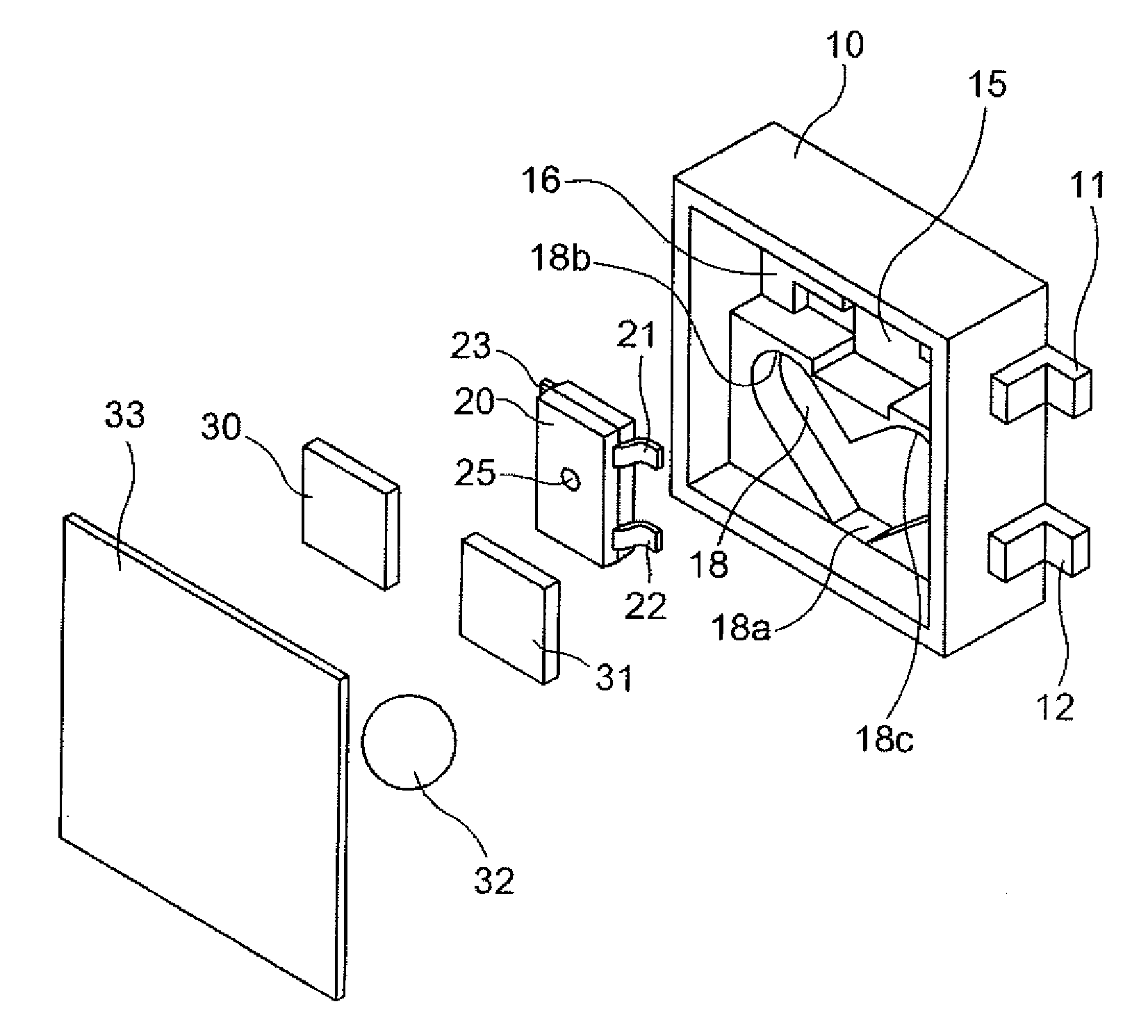
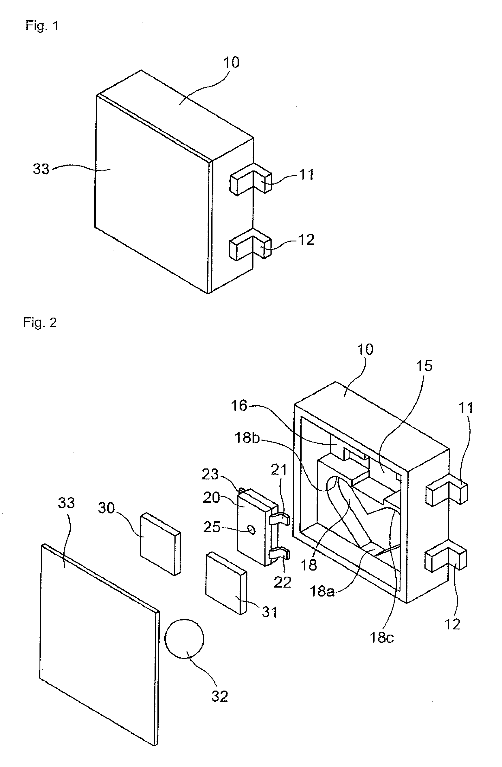
[0017]An inclination sensor according to an embodiment of the invention will described with reference to FIGS. 1 to 5. The inclination sensor of the embodiment includes a case 10, a Hall IC 20 which is of magnetic force detecting means, a pair of permanent magnets 30 and 31, a spherical rolling element 32 which is made of a magnetic material, and a cover 33. A main body of the inclination sensor of the embodiment has a width of 5 mm, a height of 5 mm, and a thickness of 2 mm. The spherical rolling element 32 has a diameter of 1.2 mm.

[0018]The case 10 is a resin molding product having a box-shape whose front view is a substantially square. Power terminals 11 and 13 and signal terminals 12 and 14 are insert-molded in sidewalls facing on both sides, respectively. In the case 10, a center recess 15 is formed in the center of an upper half of the front face to assemble the Hall IC 20 thereto. Recesses 16 and 17 are formed on both sides of the center recess 15 to dispose permanent magnets...


PUM


Abstract

A first magnetic circuit in which a magnetic line of force flows only between a pair of permanent magnets is closed, when a rolling element is located at the stationary position. When a case is inclined to roll the rolling element to a first end portion, while a second magnetic circuit in which the magnetic line of force flows only between the rolling element and one of the permanent magnets is closed, a magnetic force detecting region detects the magnetic line of force of the other permanent magnet. When the case is inclined to roll the rolling element to a second end portion, while a third magnetic circuit in which the magnetic line of force flows only between the rolling element and the other permanent magnet is closed, the magnetic force detecting region detects the magnetic line of force of one of the permanent magnets.

Description

BACKGROUND OF THE INVENTION[0001]1. Field of the Invention[0002]The present invention relates to an inclination sensor, particularly to a compact magnetic type inclination sensor used in a digital camera, a video camera, and the like.[0003]2. Description of the Related Art[0004]Conventionally, for example there is an inclination sensor, wherein a rolling element formed by a permanent magnet is rolled in a rolling groove, and a magnetic line of force of the rolling element is sensed to detect an inclination of a body to be detected using a magnetic detecting element (refer to, for example, Japanese Patent Application Laid-Open No. 2001-324324).[0005]However, because the rolling element is formed by the permanent magnet in the inclination sensor, the inclination sensor is easily affected by an external magnetic field. When an electromagnet or a magnetized metal exists around the inclination sensor, the rolling element is not smoothly rolled, and possibly the inclination state is not c...

Claims


Application Information

Patent Timeline
Patent Type & Authority Applications(United States)
IPC IPC(8): G01R33/07
CPCG01R33/07
Inventor KUROSE, IZUMI
Owner ORMON CORP
Learn More