Cylindrical coil and cylindrical micromotor using the same

a technology of cylindrical coils and micromotors, which is applied in the direction of generators/motors, magnetic circuit shapes/forms/construction, windings, etc., can solve the problems of difficult to form cylindrical micromotors having a diameter of 0.02 mm or less, mechanical precision such as roundness and straightness deterioration, and achieves the effect of reducing width/thickness, easy solving problems, and increasing the strength of sheet-shaped coils

Inactive Publication Date: 2011-07-26
NAMIKI PRECISION JEWEL CO LTD
View PDF20 Cites 11 Cited by
  • Summary
  • Abstract
  • Description
  • Claims
  • Application Information

AI Technical Summary

Benefits of technology

[0020]In the cylindrical coil according to the present invention, the coil pattern is directly formed on a surface of the cylindrical substrate, so that a process (rolling process) of rolling a sheet-shaped coil in a cylindrical shape can be omitted. For this reason, in case of manufacturing a fine cylindrical coil having a high aspect ratio, it is possible to increase a strength of the sheet-shaped coil due to a size effect of the sheet-shaped coil that a width / thickness is lowered and to easily solve the problems such as occurrence of a droplet shape (non-circular shape) of a cross section during the rolling process, deterioration in mechanical precision such as roundness and straightness, and disconnection of a wire line, particularly, a longitudinal wire line due to a shearing stress caused from a difference of inner and outer diameters.
[0021]According to the present invention, since the cylindrical coil can be maintained to have a high mechanical precision such as roundness and straightness, it is possible to reduce an air gap and a magnetic gap in the implementation of a micromotor having a small size and a small diameter by using the cylindrical coil. Therefore, permeance coefficient is increased, so that a magnetic efficiency can be improved. As a result, a torque constant or the like can be improved.
[0022]In addition, since a fine coil pattern groove can be formed by using the nano-imprinting method, the groove can be directly filled with a conductor to form a coil pattern, so that it is possible to form a fine coil pattern.
[0023]In addition, a plurality of coil pattern layers and a plurality of insulating layers are formed, and the layered coil patterns can be electrically interconnected to each other with a conductor filled in a through-hole formed by performing a hole forming process with a laser, so that it is possible to form a multi-layered cylindrical coil. In addition, the number of windings can be increased, so that it is possible to improve a torque constant or the like.
[0024]A width of the coil pattern of the cylindrical coil is formed to be 20 μm or less, so that a fine coil pattern can be formed to have a coil pattern width which is narrower than the width limitation of wire line of a conventional coil. Therefore, it is possible to implement a cylindrical coil having a smaller size and a smaller diameter.
[0025]In addition, by using the cylindrical coil according to the present invention to a cylindrical micromotor, it is possible to implement a cylindrical micrometer having a small size and a small diameter.

Problems solved by technology

Therefore, it is difficult to form a cylindrical micromotor having an outer diameter of 1.5 mm or less, particularly, 1.0 mm or less due to the following reasons.
Firstly, since a shape of the coil tends to be deformed during the formation of the coil, mechanical precision such as roundness and straightness deteriorates.
In addition, due to a limitation to manufacturing of the self-fusing copper wire line, it is difficult to form a wire line having a diameter of 0.02 mm or less.

Method used


Image

  • Cylindrical coil and cylindrical micromotor using the same
  • Cylindrical coil and cylindrical micromotor using the same
  • Cylindrical coil and cylindrical micromotor using the same

Examples


Embodiment Construction

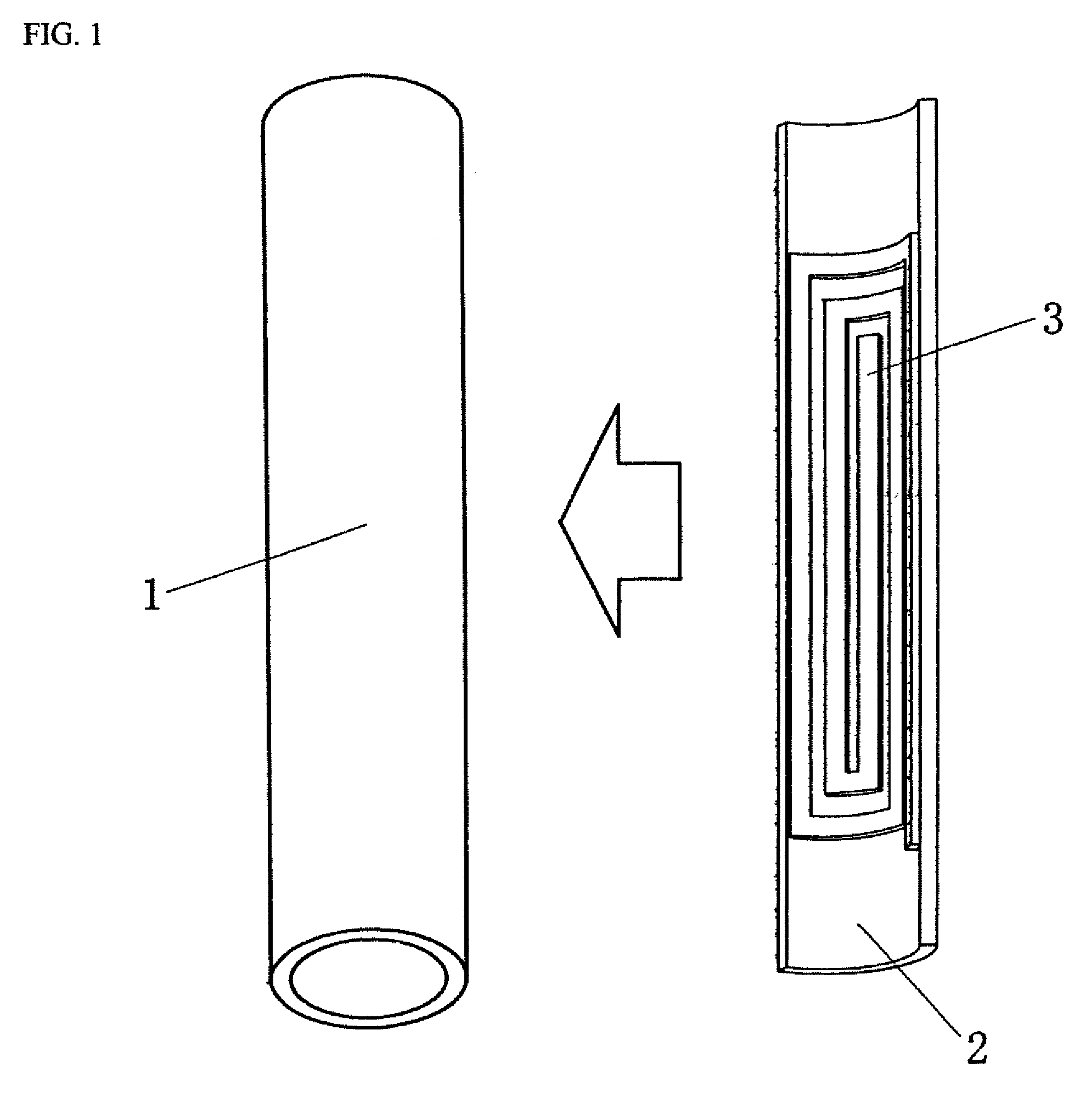
[0026]FIG. 1 is a schematic view illustrating a process of forming a coil pattern groove by using a nano-imprinting method according to an embodiment of the present invention. In the embodiment, the aforementioned thermal-type nano-imprinting method is used.

[0027]In the thermal-type nano-imprinting method, a mold 2 which has a arc-shaped cross section and in which a fine protrusion 3 having a shape of a coil pattern is formed on an inner surface thereof is set. The mold 2 together with a cylindrical substrate 1 made of an insulating thermoplastic resin is heated up over a glass transition temperature of the cylindrical substrate 1. The mold 2 is pressed on the cylindrical substrate 1 for a predetermined time interval. The cylindrical substrate 1 and the mold 2 are cooled down below the glass transition temperature. The mold 2 is peeled off from the cylindrical substrate 1.

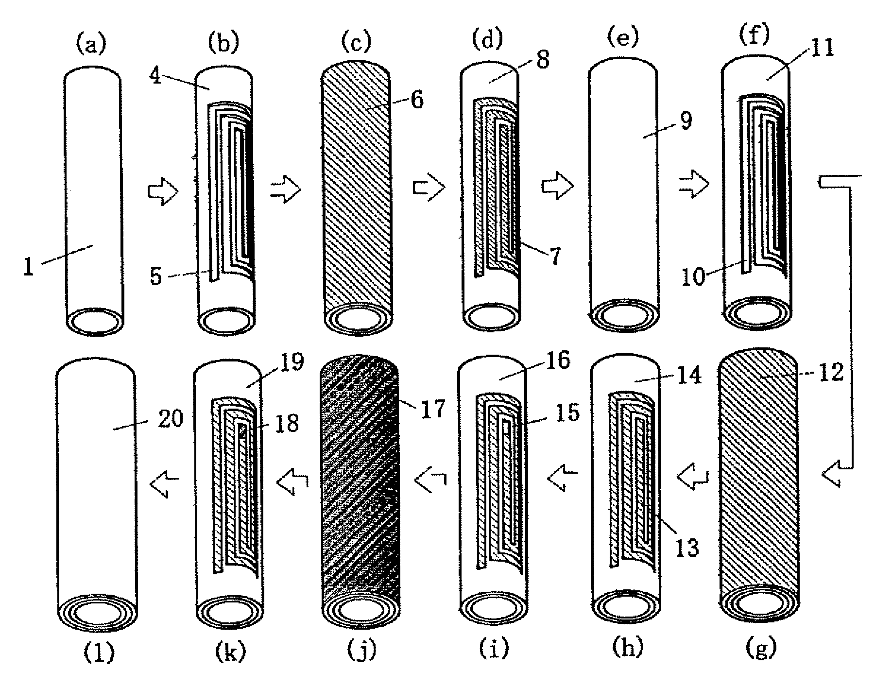
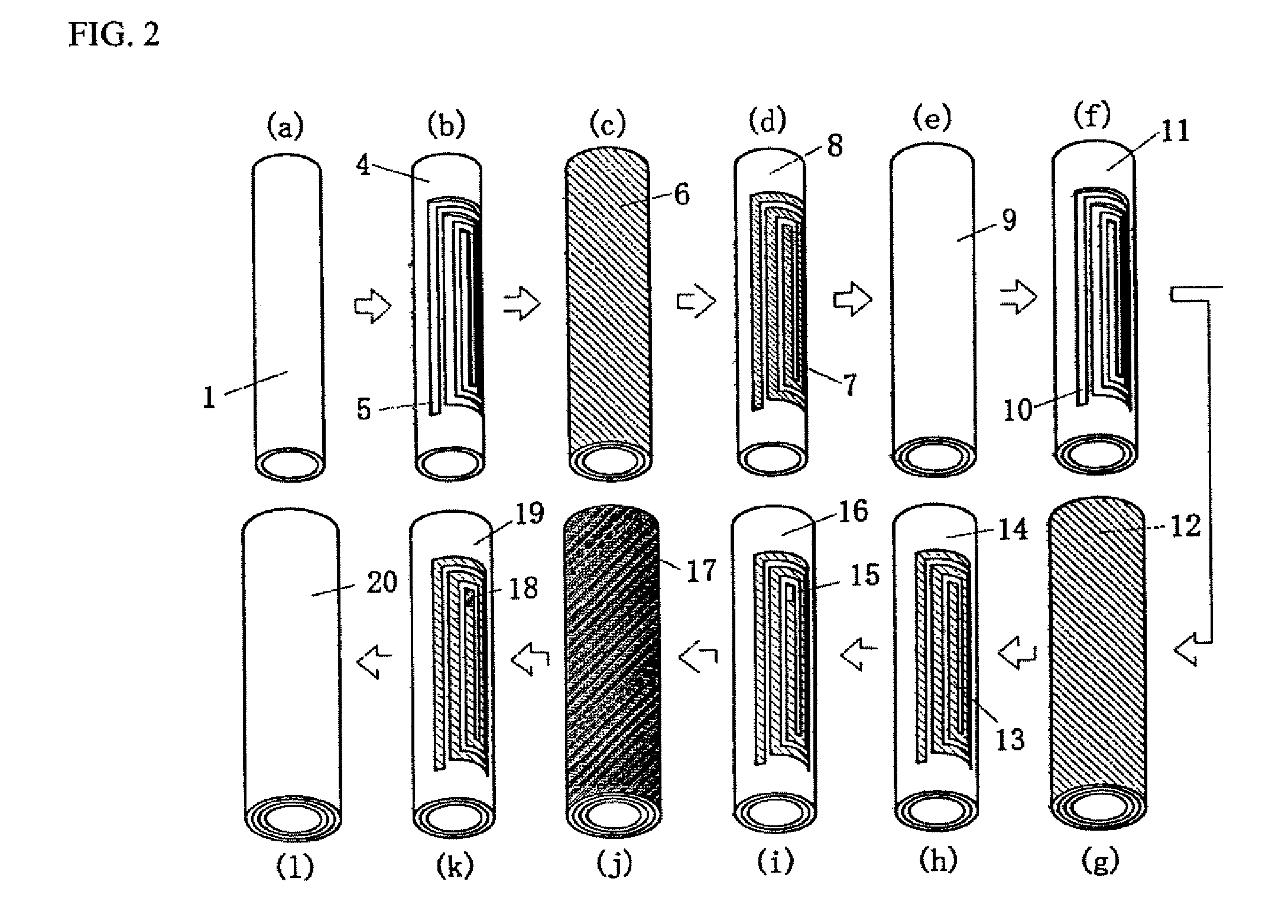
[0028]FIGS. 2(a) to 2(l) are schematic views illustrating a process of forming a cylindrical coil according to t...


PUM

PropertyMeasurementUnit
widthaaaaaaaaaa
outer diameteraaaaaaaaaa

Abstract

A high-precision cylindrical coil having a high-precision fine coil pattern and a high mechanical precision such as fine roundness and no axial runout, and a cylindrical micrometer using the cylindrical coil are provided.In a cylindrical coil, a plurality of layers of coil patterns formed by filling the coil pattern grooves formed on a cylindrical substrate with a conductor and a plurality of insulating layers coating the cylindrical substrate are formed, the layers of coil patterns are electrically interconnected to each other by filling a through-hole formed by performing a hole forming process with a conductor, and the outmost layer is made of an insulating material.

Description

FIELD OF THE INVENTION[0001]The present invention relates to a cylindrical coil having a extremely small diameter and a fine coil pattern and a cylindrical micromotor using the same.BACKGROUND ART[0002]Recently, as high-performance instrument having a built-in actuator has been widely used in fields of medical instrument, analytical instrument, or micro-machine, a small-sized micromotor has been demanded.[0003]In the implementation of the micromotor having a small size, particularly, a small diameter, a coil built in the micrometer is necessarily formed in a small size and finely.[0004]Generally, the coil is formed by winding a copper line which is coated with an insulator such as polyurethane around a core having a slot. Otherwise, the coil may be formed as a coreless coil. Namely, a self-fusing copper line is prepared by additionally forming a fusing layer on the outmost layer of the insulator-coated copper line. The coreless coil is obtained by forming the self-fusing copper line...

Claims


Application Information

Patent Timeline
Patent Type & Authority Patents(United States)
IPC IPC(8): H02K1/04H02K5/00
CPCH02K3/26H02K23/26H02K3/47Y10T29/49009
Inventor NAKAMURA, KAZUYAHIYAMA, YOSHIHITOIMAIZUMI, NOBUO
Owner NAMIKI PRECISION JEWEL CO LTD
Why Eureka
Try Eureka