
Generator structure

A generator and claw pole technology, applied in the magnetic circuit shape/style/structure, synchronous motor with stationary armature and rotating magnet, bicycle accessories, etc. Problems such as the magnetic flux of the wire tube iron core and the difficulty of effectively reducing the overall diameter can be achieved to increase the output efficiency of the induced voltage, reduce the overall volume, and achieve the effects of good voltage output performance

Active Publication Date: 2010-09-29
IND TECH RES INST
View PDF13 Cites 0 Cited by
  • Summary
  • Abstract
  • Description
  • Claims
  • Application Information

AI Technical Summary

Problems solved by technology

[0004] 1. The magnet is a round tube that wraps around the stator core, which is bulky and expensive to manufacture;
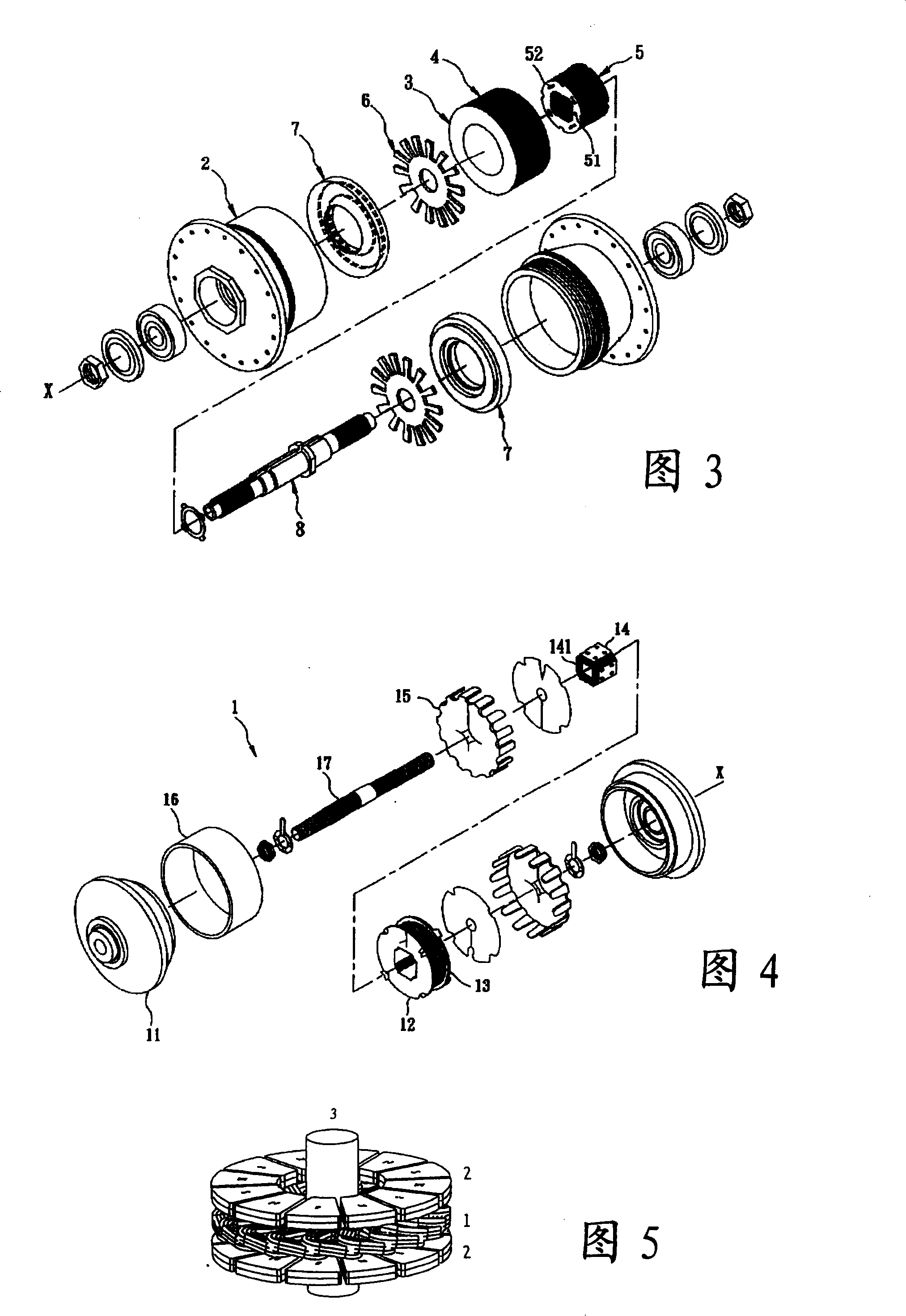
[0005] 2. The magnetic force line is guided by the pole piece (claw pole) and passes through more than two turns in the geometric direction, thus reducing the magnetic flux passing through the solenoid core;
[0006] 3. Because the stator core must be made into a 3D shape, and the number of magnetic flux guidance turns is more than two times, and the magnetic field between each pole piece (claw pole) is easy to interfere with each other, making the whole efficiency low
[0008] see more Figure 5 , U.S. Early Publication No. 20040135452 "Flat Rotary Electric Generator", said patent provides a flat rotary generator design, each corresponding magnetic pole set 2 will cooperate with a solenoid coil 1, because the solenoid coil 1 The winding has a certain size limit. When adopting a multi-pole design configuration, the size of the hollow part after the diameter of the hollow part is divided into equal parts, so it is difficult to effectively reduce the overall diameter. In order to increase the power generation, the volume must be increased. Therefore, the structure cannot achieve both battery miniaturization and power density

Method used


Image

  • Generator structure
  • Generator structure
  • Generator structure

Examples


Embodiment Construction

[0063] The following will describe the technical means and effects used by the present invention to achieve the purpose with reference to the accompanying drawings, and the embodiments listed in the following drawings are only for auxiliary illustration, but the technical means of this case are not limited to the listed drawings.

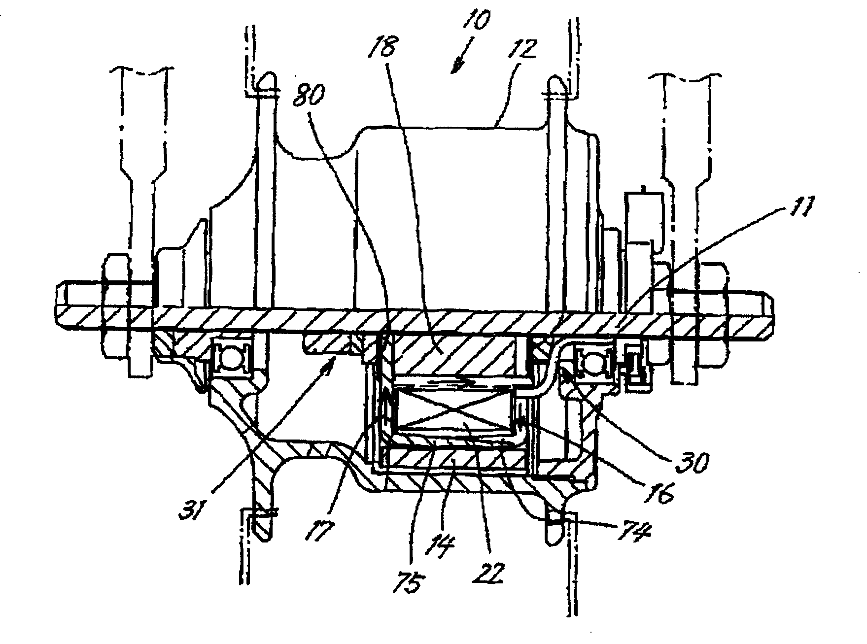
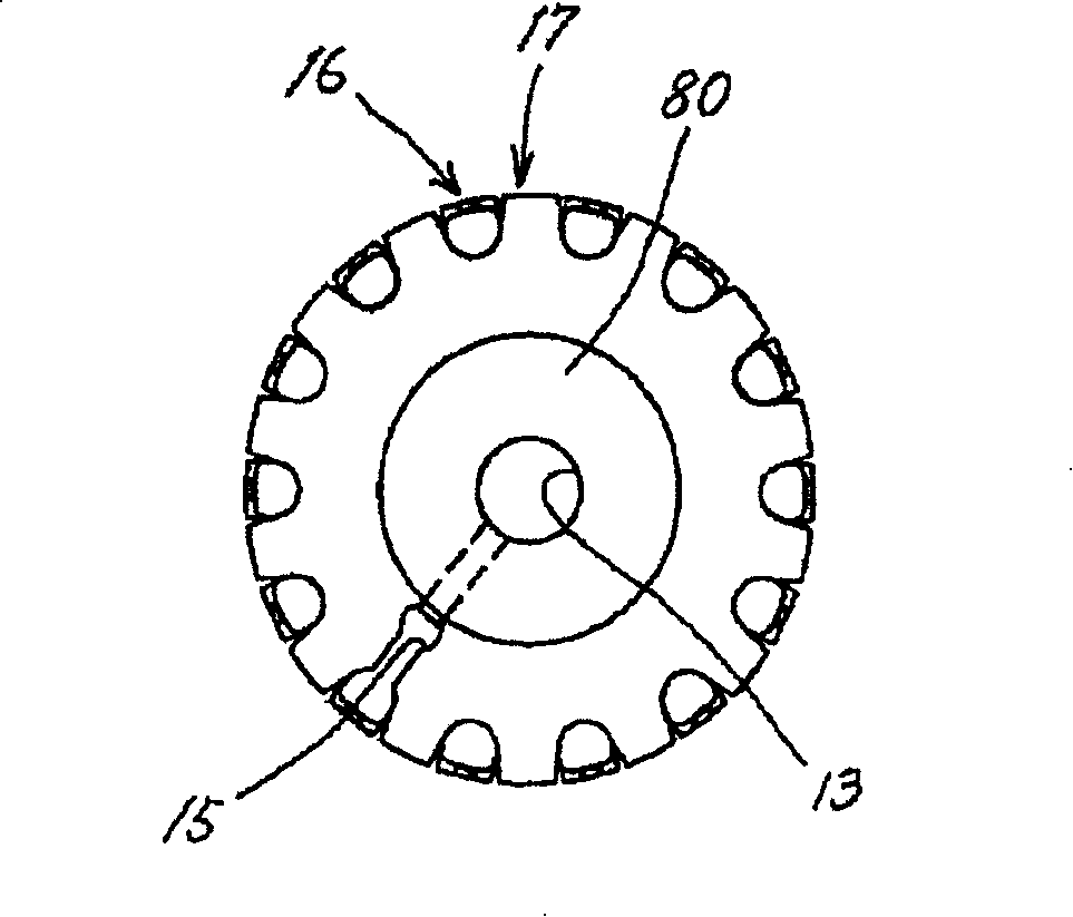
[0064] see Figure 6 to Figure 8 As shown, in a preferred embodiment of the present invention, the generator structure 10 is a single-sided magnet structure, which includes a claw pole set 20, a mandrel 30, an iron core 40, a connecting piece 50, a screw Line pipe coil 60 ( Image 6 The solenoid coil 60 ), a magnet 70 and a back iron group 80 are not shown.

[0065] The claw pole set 20 includes an outer claw pole assembly 21 and an inner claw pole assembly 22. The outer claw pole assembly 21 is used to form an external magnetic circuit, which is composed of an outer tube 211 and a plurality of outer claws pole 212, the outer claw pole 212 is arra...


PUM


Abstract

This invention relates to a generator structure including at least a magnet with over two magnetizing pole numbers and at least one claw-pole set composed of a set of internal claw poles and a set of outer claw poles set interluded and used in guiding magnetic flux, in which, said internal claw pole is connected with a core with the outer diameter smaller than the magnet for conducting the loop of the internal and outer claw poles, and a solenoid coil is winded around the core and pole numbers of the internal or the outer pole is half of the charged pole number of the magnet, when the magnet moves relatively to the claw poles, induction electromotive force is generated by continuous change of flux in the solenoid.

Description

technical field [0001] The present invention relates to a generator structure, in particular to a generator with multi-pole magnetized magnets in flat circular or other geometric forms, integrated with the iron core, and claw pole groups wrapped outside the solenoid Design, its overall design is simple, easy to manufacture, small in size, relatively good voltage output performance at low speed, suitable for generator application or manufacturing and other related technical fields. Background technique [0002] With the promotion of less battery movement, the design of miniaturized and high-efficiency generators has become an important issue. One of the product examples is bicycle generators, and the built-in hub generator is recognized as a design method with less resistance and more beautiful appearance. In the limited space of the hub, in accordance with the relevant bicycle lighting regulations, it must be able to drive a 12Ω (ohm) light bulb at a low speed (about 5Km / h),...

Claims


Application Information

Patent Timeline
Patent Type & Authority Patents(China)
IPC IPC(8): H02K21/12H02K21/24H02K1/27H02K1/12H02K7/18B62J6/12
Inventor 彭文阳张复瑜郑庆祥
Owner IND TECH RES INST
Learn More