
Cylindrical linear motor

a linear motor and cylindrical technology, applied in the direction of dynamo-electric machines, magnetic circuit rotating parts, magnetic circuit shapes/forms/construction, etc., can solve the problems of difficult to further improve the thrust of the cylindrical linear motor, and achieve the effect of increasing the magnetic field acting, reducing the magnetic resistance, and high residual magnetic flux

Active Publication Date: 2020-07-30
KYB CORP
View PDF0 Cites 0 Cited by
  • Summary
  • Abstract
  • Description
  • Claims
  • Application Information

AI Technical Summary

Benefits of technology

The invention is a cylindrical linear motor that improves thrust by increasing the residual magnetic flux density of the permanent magnet of the main magnetic pole. This is achieved by making the coercive force of the permanent magnet of the sub magnetic pole higher than that of the main magnetic pole, preventing demagnetization. This allows for a larger axial length of the permanent magnet of the main magnetic pole to reduce magnetic resistance and increase the magnetic field acting on the core. The technical effect is an effective improvement in motor performance.

Problems solved by technology

However, since the permanent magnets of the main magnetic pole and the sub magnetic pole have the same axial length, the magnetic resistance between the permanent magnet of the main magnetic pole and the armature is large, and even if the residual magnetic flux density of the permanent magnet of the main magnetic pole is increased, it is difficult to further improve the thrust of the cylindrical linear motor.

Method used


Image

  • Cylindrical linear motor
  • Cylindrical linear motor
  • Cylindrical linear motor

Examples


Embodiment Construction

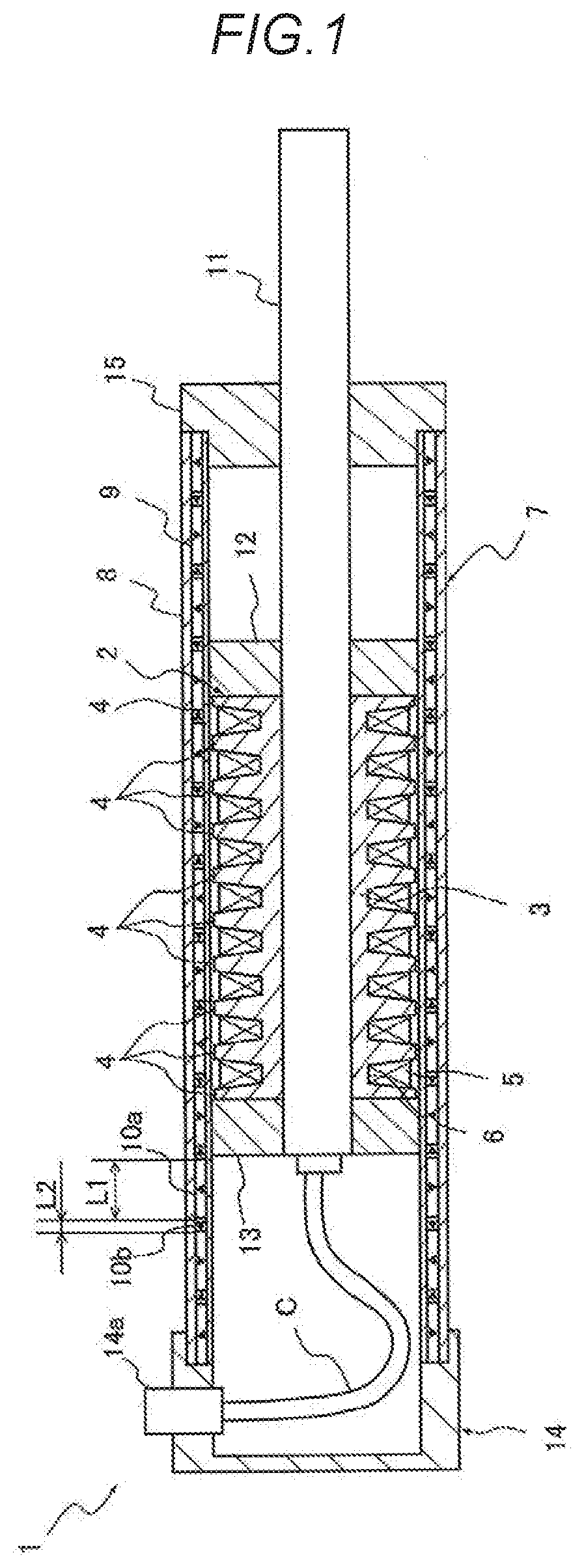
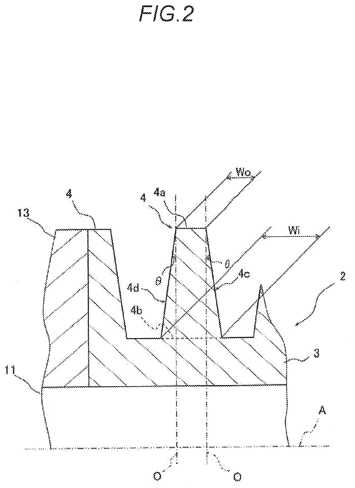
[0013]Hereinafter, the present invention will be described based on the embodiments illustrated in the drawings. As shown in FIG. 1, a cylindrical linear motor 1 according to one embodiment includes a core 2 having a cylindrical yoke 3 and a plurality of annular teeth 4 provided on the outer periphery of the yoke 3; a winding 5 mounted between the teeth 4, 4; and a field 7which is cylindrical and into which the core 2 is inwardly inserted movably in the axial direction.

[0014]Hereinafter, each portion of the cylindrical linear motor 1 will be described in details. The core 2 is configured to include a cylindrical yoke 3; and a plurality of teeth 4 which are annular and are provided on the outer periphery of the yoke 3 at intervals in the axial direction, and serve as a movable element.

[0015]The yoke 3 has a cylindrical shape as described above, and the thickness thereof is secured so that the sectional area thereof is equal to or larger than an area of the cross section obtained by c...


PUM


Abstract

To achieve the above object, a cylindrical linear motor of the present invention includes a cylindrical linear motor includes: a core having a cylindrical yoke, and a plurality of teeth that are annular and are provided at intervals in an axial direction on an outer periphery of the yoke; a winding mounted in slots between the teeth; and a field which is cylindrical and in which the core is inwardly inserted movably in the axial direction to arrange N poles and S poles alternately in the axial direction, wherein the field has permanent magnets of a main magnetic pole radially magnetized and permanent magnets of a sub magnetic pole axially magnetized that are alternately arranged in a Halbach array in the axial direction, an axial length of the permanent magnet of the main magnetic pole is longer than an axial length of the permanent magnet of the sub magnetic pole, and the permanent magnet of the sub magnetic pole has a coercive force higher than that of the permanent magnet of the main magnetic pole.

Description

TECHNICAL FIELD[0001]The present invention relates to a cylindrical linear motor.BACKGROUND ART[0002]Some cylindrical linear motors include, for example, an armature having a cylindrical core having a plurality of teeth arranged side by side in the axial direction on the outer periphery and U-phase, V-phase, and W-phase windings mounted in slots between teeth; and a stator consisting of a cylindrical yoke provided on the outer periphery of the armature and a plurality of permanent magnets attached to the inner periphery of the base so that the S poles and the N poles are alternately arranged in the axial direction.[0003]In the cylindrical linear motor configured in this way, when the U-phase, V-phase, and W-phase windings of the armature are appropriately energized, the armature is attracted to the permanent magnet, and the armature is driven as a movable element axially with respect to the stator.[0004]In such a cylindrical linear motor, for example, as disclosed in JP2007-19127A, ...

Claims


Application Information

Patent Timeline
Patent Type & Authority Applications(United States)
IPC IPC(8): H02K41/03
CPCH02K41/03H02K1/27H02K41/031H02K1/17
Inventor KANO, YOSHIAKISATOU, KOUSUKEHAKAMADA, SHINICHIROU
Owner KYB CORP
Learn More