
Stator of linear motor and linear motor and compressor

A linear motor and straight stator technology, applied in electromechanical devices, electrical components, magnetic circuit shape/style/structure, etc., can solve problems such as magnetic loss, reduce magnetic loss, reduce cost, and reduce magnetic permeability resistance. Effect

Active Publication Date: 2019-11-05
TONGJI UNIV
View PDF5 Cites 0 Cited by
  • Summary
  • Abstract
  • Description
  • Claims
  • Application Information

AI Technical Summary

Problems solved by technology

However, neither of the two patents fundamentally solves the problem of the combined gap. After the electrodes are energized, the combined gap will still form magnetic resistance and cause magnetic loss.

Method used


Image

  • Stator of linear motor and linear motor and compressor
  • Stator of linear motor and linear motor and compressor
  • Stator of linear motor and linear motor and compressor

Examples


Embodiment 1

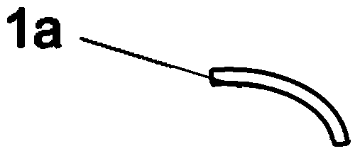
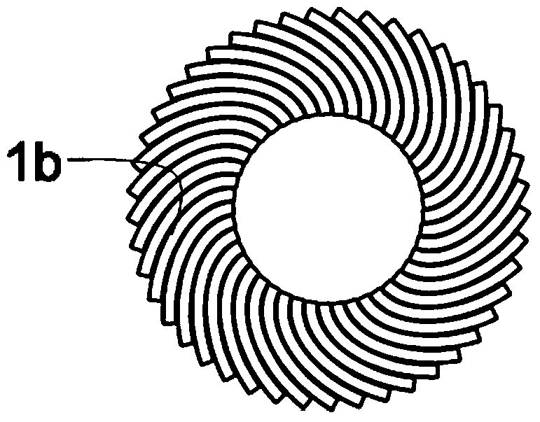
[0064] As shown in Figure 1-3, an inner stator for a linear motor, the inner stator adopts the following Figure 1a-1b The first type of inner stator sheet 1a is processed. The first type of inner stator sheet 1a is stamped from a straight stator sheet into an arc-shaped stator sheet according to a certain radian, and it can also be bent by other methods. Several first-type inner stator pieces 1a are welded into an annular first-type inner stator 1b (such as Figure 2a-2b As shown), the design principle of the arc is that the adjacent first inner stator pieces 1a are tightly fitted, and there is no gap as much as possible;

[0065] Because the outer circle of the inner stator 1b is made up of the side surfaces of a piece of plate, it is not too smooth, so secondary processing can be carried out. On the basis of the first type of inner stator 1b, its outer circumference is further cut to form as Figure 3a-3b The second inner stator 1c of the structure shown.

[0066] The nu...

Embodiment 2

[0070] As shown in Figure 4-6, an inner stator used for a linear compressor motor, wherein the inner stator adopts such as Figure 4a-4b The second type of inner stator sheet 2a after the arc stamping process shown is welded, and the second type of inner stator sheet 2a after the arc stamping process has grooves, so that the third type of stator sheet 2a welded by it Inner stator 2b (such as Figures 5a-5b There is a groove a on the outer periphery of the above), the groove a can be used to place magnets, so that the magnets and the third inner stator 2b form a whole without additional magnet fixing devices. On the basis of the third inner stator 2b, its outer circumference is further cut to form as Figures 6a-6b In the fourth type of inner stator 2c shown, the above-mentioned adjacent second type inner stator pieces 2a are tightly bonded without gaps; the number of second type inner stator pieces 2a is determined by the thickness of each second type inner stator piece 2a A...

Embodiment 3

[0075] A stator for a linear compressor motor, including an inner stator and an outer stator, as shown in FIG. The first type of outer stator 3b mentioned above, the second type of inner stator 1c is arranged in the inner ring of the first type of outer stator 3b.


PUM


Abstract

The invention relates to a stator used for a linear compressor motor, the linear motor and a compressor. The stator is composed of arc stator pieces. According to the stator, firstly straight stator pieces are bent into the arc shape to act as the arc stator pieces, and then the arc stator pieces form the stator. The stator can be an internal stator or an external stator. The external circle of the internal stator can be provided with a circle of grooves. The circumference of the internal side of the external stator can be provided with a groove. The internal stator and the external stator adopted in the linear motor are the internal stator and the external stator or the internal stator and the conventional external stator. The motor adopted in the compressor is the linear motor. Compared with the stators in the prior art, the filling rate of the linear motor stator can be close to 100% so that the magnetic loss caused by the combination gap in the stator can be reduced and the efficiency of the motor can be enhanced.

Description

technical field [0001] The invention relates to the field of refrigerators, in particular to a stator of a linear motor and a linear motor and a compressor using the stator. Background technique [0002] The linear compressor uses a linear motor to directly drive the piston to perform linear reciprocating motion. Compared with the traditional rotary motor-driven compressor, it has less vibration, less mechanical loss, high efficiency, and simple structure. The linear motor includes an inner stator, an outer stator and a coil. There is a certain gap between the inner stator and the outer stator. A mover made of a magnet is arranged in the middle of the gap, and the mover is connected to the piston in the cylinder through a bracket. When the coil is energized, a magnetic field will be generated between the inner stator and the outer stator. Under the action of the changing electromagnetic field, the reciprocating motion of the mover drives the reciprocating motion of the pisto...

Claims


Application Information

Patent Timeline
Patent Type & Authority Patents(China)
IPC IPC(8): H02K1/12H02K16/00
CPCH02K1/12H02K16/00
Inventor 朱绍伟
Owner TONGJI UNIV
Learn More