
Channel state information measurement and feedback for transmission mode switching

a transmission mode and information measurement technology, applied in the field of communication systems, can solve the problems of csi feedback becoming burdensome, requiring an undesirable amount of overhead, and a particular transmission mode may be used, so as to limit the complexity of blind detection, and reduce the number of possible pdcch candidates

Active Publication Date: 2019-12-19
QUALCOMM INC
View PDF18 Cites 6 Cited by
  • Summary
  • Abstract
  • Description
  • Claims
  • Application Information

AI Technical Summary

Benefits of technology

The patent text describes a solution for a network to dynamically switch transmission modes for a user equipment (UE) without needing to establish a new connection. This is done by configuring the UE with a combination of transmission modes using RRC signaling. The text also mentions that different sizes of DCI formats can be used to indicate different transmission modes to reduce blind detection by the UE. However, the text recognizes that providing dynamic and corresponding channel state information (CSI) feedback can become burdensome and require additional overhead. Therefore, the patent seeks to address this issue by proposing a solution for more efficient use of additional overhead. The technical effects of this patent are improved efficiency and reduced burden on the UE by dynamically switching transmission modes and limiting the burden on the network by optimizing CSI feedback.

Problems solved by technology

Problems may arise for a UE using a particular transmission mode if network conditions change while the UE is connected to the network.
However, CSI feedback may become burdensome and require an undesirable amount of overhead for combinations of transmission modes.

Method used


Image

  • Channel state information measurement and feedback for transmission mode switching
  • Channel state information measurement and feedback for transmission mode switching
  • Channel state information measurement and feedback for transmission mode switching

Examples


Embodiment Construction

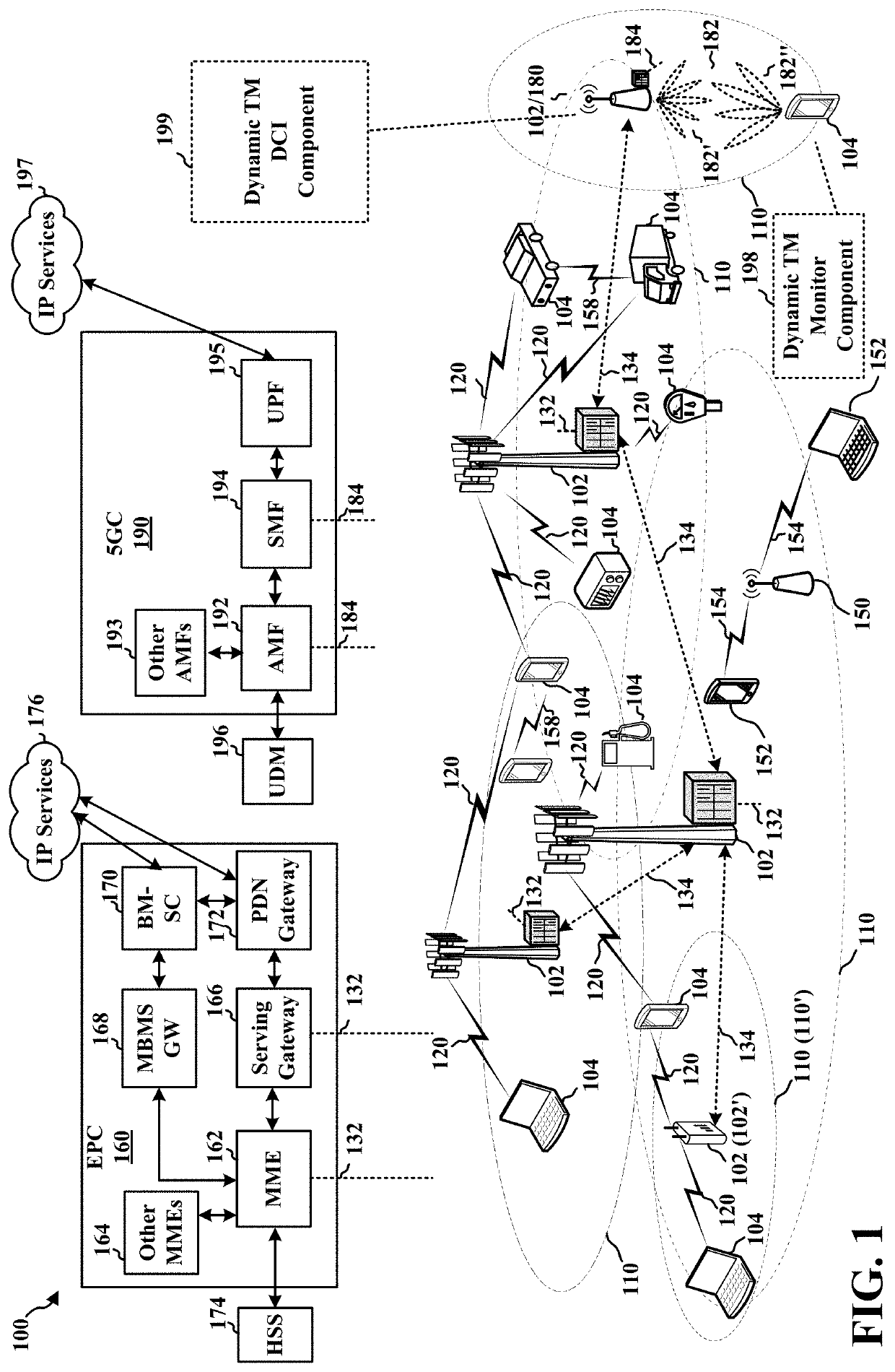
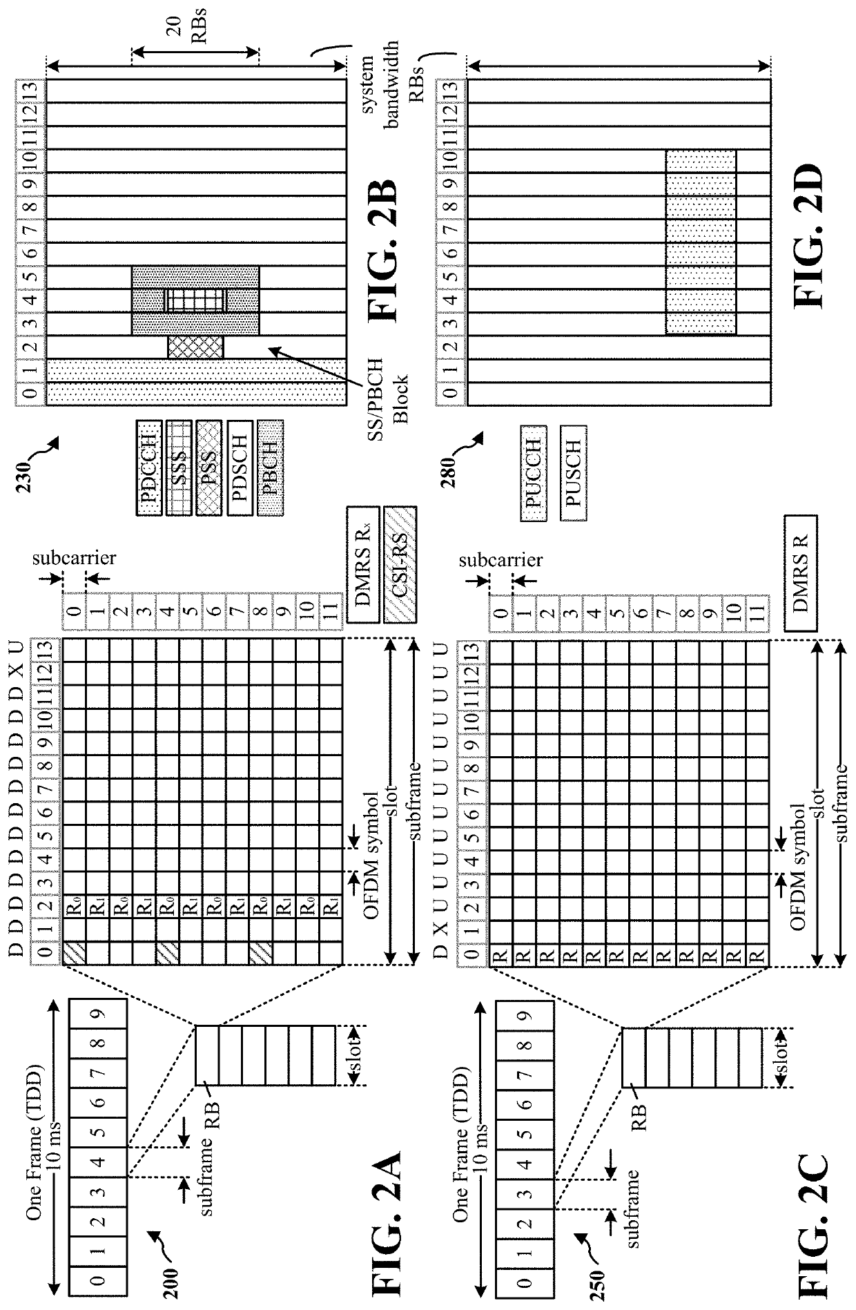
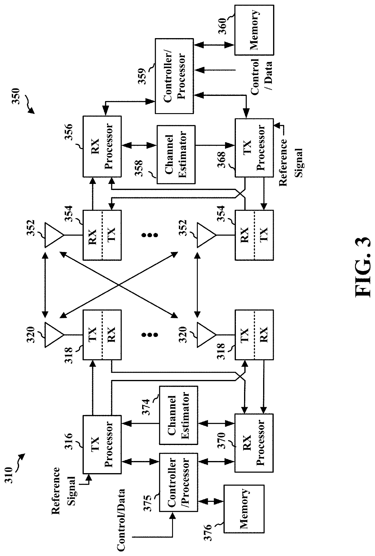
[0036]The detailed description set forth below in connection with the appended drawings is intended as a description of various configurations and is not intended to represent the only configurations in which the concepts described herein may be practiced. The detailed description includes specific details for the purpose of providing a thorough understanding of various concepts. However, it will be apparent to those skilled in the art that these concepts may be practiced without these specific details. In some instances, well known structures and components are shown in block diagram form in order to avoid obscuring such concepts.

[0037]Several aspects of telecommunication systems will now be presented with reference to various apparatus and methods. These apparatus and methods will be described in the following detailed description and illustrated in the accompanying drawings by various blocks, components, circuits, processes, algorithms, etc. (collectively referred to as “elements...


PUM


Abstract

A method, apparatus, and computer-readable medium are presented that enables dynamic switching of transmission modes by a UE. A UE may be configured with a transmission mode. However, the configured transmission mode might not meet the needs of changing network conditions. Aspects presented herein enable a base station to assist a UE in switching between transmission modes. The base station may signal a combination of transmission modes to the UE, e.g., including at least a first transmission mode and a second transmission mode. The UE may then monitor for one or more DCI formats in order to determine whether to switch among transmission modes from the indicated combination of transmission modes

Description

CROSS REFERENCE TO RELATED APPLICATIONS[0001]This application claims the benefit of U.S. Provisional Application Ser. No. 62 / 684,675, entitled “CHANNEL STATE INFORMATION MEASUREMENT AND FEEDBACK FOR TRANSMISSION MODE SWITCHING” and filed on Jun. 13, 2018, and claims the benefit of U.S. Provisional Application Ser. No. 62 / 684,684, entitled “TRANSMISSION MODE SWITCHING” and filed on Jun. 13, 2018, which are expressly incorporated by reference herein in their entirety.BACKGROUNDTechnical Field[0002]The present disclosure relates generally to communication systems, and more particularly, to wireless communication involving transmission mode (TM) switching.INTRODUCTION[0003]Wireless communication systems are widely deployed to provide various telecommunication services such as telephony, video, data, messaging, and broadcasts. Typical wireless communication systems may employ multiple-access technologies capable of supporting communication with multiple users by sharing available system ...

Claims


Application Information

Patent Timeline
IPC IPC(8): H04L1/00H04B7/0456H04B7/06H04W72/04H04L5/00
CPCH04W72/042H04B7/0456H04L5/0053H04L1/003H04B7/0626H04L5/0057H04L5/005H04L5/0051H04L5/0091H04B7/0689H04B7/024H04B7/0452H04L1/0026H04W72/23H04L1/0027H04L1/0025H04W88/06
Inventor LIU, LERICO ALVARINO, ALBERTO
Owner QUALCOMM INC
Learn More