Smart surface

a technology of smart surfaces and sensors, applied in the field of smart surfaces, can solve problems such as the difficulty of integrating bulky sensors into surfaces

Active Publication Date: 2019-12-26
TDK CORPARATION
View PDF45 Cites 2 Cited by
  • Summary
  • Abstract
  • Description
  • Claims
  • Application Information

AI Technical Summary

Problems solved by technology

However, it is challenging to integrate bulky sensors into surfaces, e.g., surface of a vehicle.

Method used


Image

  • Smart surface
  • Smart surface
  • Smart surface

Examples


Embodiment Construction

[0014]Before various embodiments are described in greater detail, it should be understood by persons having ordinary skill in the art that the embodiments are not limiting, as elements in such embodiments may vary. It should likewise be understood that a particular embodiment described and / or illustrated herein has elements which may be readily separated from the particular embodiment and optionally combined with any of several other embodiments or substituted for elements in any of several other embodiments described herein.

[0015]It should also be understood by persons having ordinary skill in the art that the terminology used herein is for the purpose of describing the certain concepts, and the terminology is not intended to be limiting. Unless indicated otherwise, ordinal numbers (e.g., first, second, third, etc.) are used to distinguish or identify different elements or steps in a group of elements or steps, and do not supply a serial or numerical limitation on the elements or s...


PUM

PropertyMeasurementUnit
heightaaaaaaaaaa
temperatureaaaaaaaaaa

Abstract

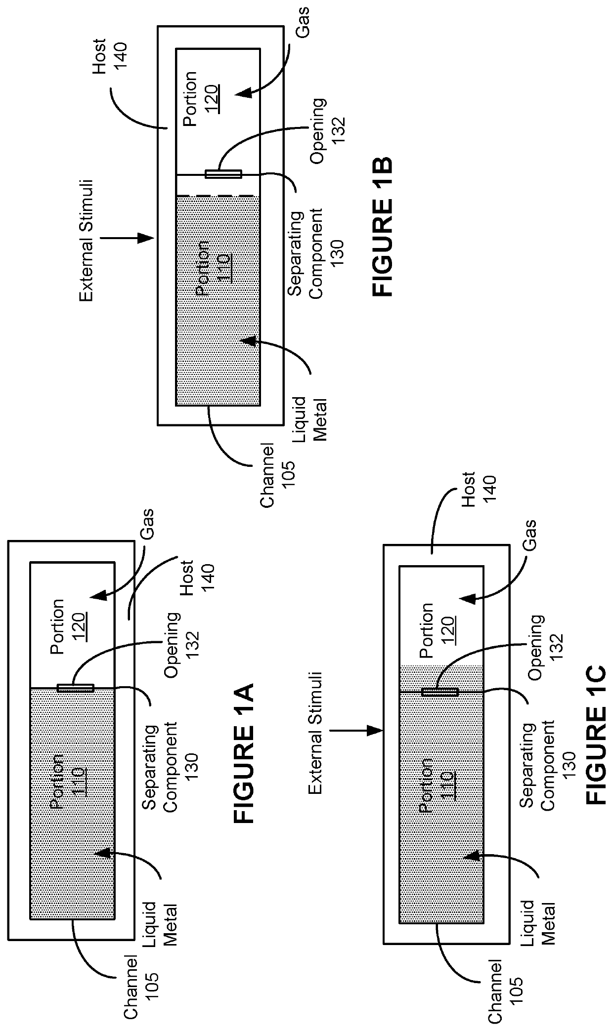
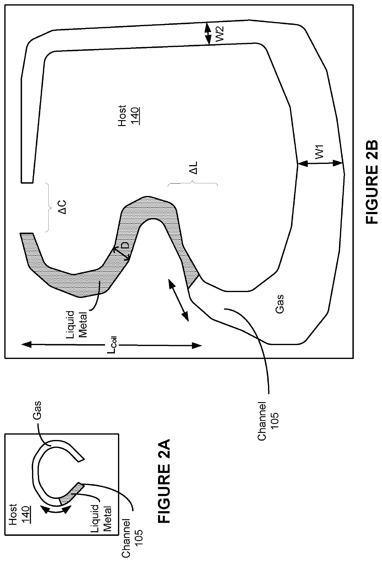
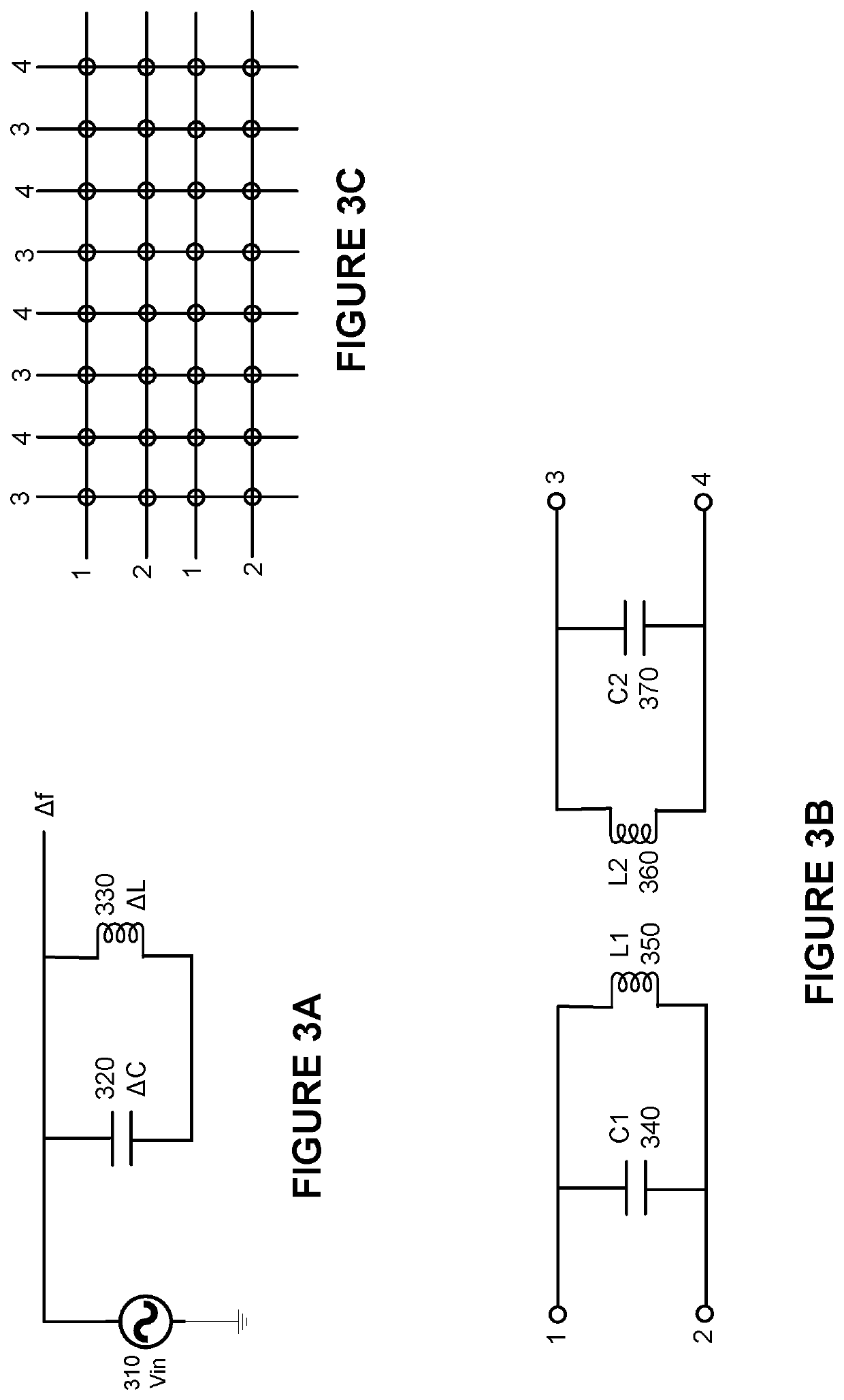
A device includes a channel, a slit, and a cap. The channel is formed on a surface of the device. The slit separates the channel to a first portion and a second portion. The first portion comprises liquid metal, e.g., gallatin. The second portion comprises gas. The liquid metal moves within the channel between the first and the second portions in response to external stimuli, e.g., pressure. The liquid metal moving within the channel changes electrical characteristics, e.g., capacitive value, inductance value, resistance value, resonance frequency, etc., of the device.

Description

BACKGROUND[0001]Many industries have experienced an increased use of electronics and smart devices in recent years. The increased use of electronic devices, for example, advent of artificial intelligence, self-driving vehicles, smart homes, and Internet-of-things (IOTs) has increased the need to gather data and to use sensors. However, it is challenging to integrate bulky sensors into surfaces, e.g., surface of a vehicle.SUMMARY[0002]Accordingly, there is a need for sensors that can be integrated into any surface and to make that surface a smart surface by collecting data regarding, for example, any ambient condition.[0003]In some embodiments, a device includes a channel, a slit, and a cap. The channel is formed on a surface of the device. The slit separates the channel to a first portion and a second portion. The first portion comprises liquid metal, e.g., gallatin. The second portion comprises gas. The liquid metal moves within the channel between the first and the second portions...

Claims


Application Information

Patent Timeline
Patent Type & Authority Applications(United States)
IPC IPC(8): G01L5/16G01F23/24G01R27/22G01R1/04G01R1/20
CPCG01F23/24G01R27/22G01R1/04G01R3/00G01R1/206G01L5/161G01K5/02G01D5/12G01K5/18G01P15/006G01L9/0091
Inventor SETHI, RAKESH
Owner TDK CORPARATION
Why Eureka
Try Eureka