Thermal performance optimization in a thermal therapy device

Active Publication Date: 2020-01-02
AVENT INC
View PDF0 Cites 1 Cited by
  • Summary
  • Abstract
  • Description
  • Claims
  • Application Information

AI Technical Summary

Benefits of technology

[0094]In some embodiments, the method further includes directing a cross-tank flow of the cold and hot liquids between the cold and hot reservoirs via a conduit operated by a cross-tank valve, where the cross-tank flow is dire

Problems solved by technology

However, use of hot and cold water baths

Method used


Image

  • Thermal performance optimization in a thermal therapy device
  • Thermal performance optimization in a thermal therapy device
  • Thermal performance optimization in a thermal therapy device

Examples


Embodiment Construction

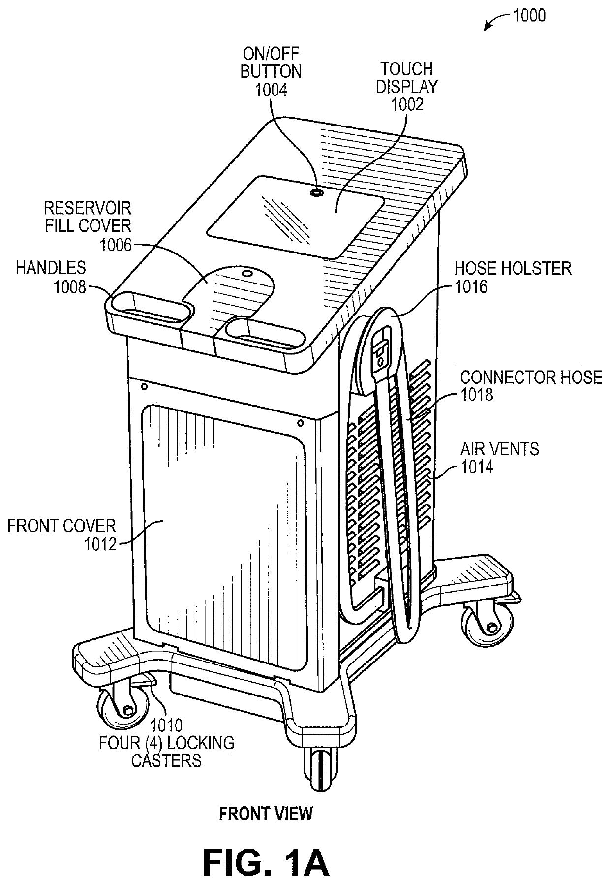
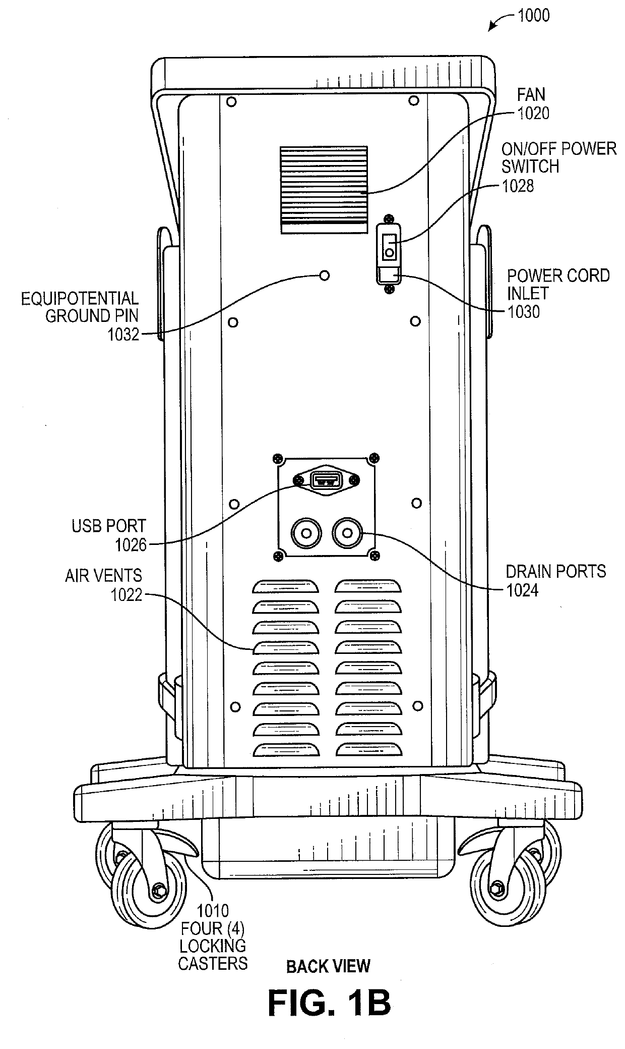
[0115]FIGS. 1A-1B and illustrate a system 1000 for providing cold, heat / hot / warm (hereafter referred to as “hot”), and / or rapid contrast therapy, which involves rapidly alternating between cold therapy and hot therapy. The system can circulate cold or warm fluid, such as water, through a hose, into a therapy wrap, and then back to the fluid reservoirs of the system. The system can utilize a vapor compression system or other chiller technology to cool the cold water reservoir, and immersion heaters can be used to heat the hot water reservoir. The system can have two or more ports, in order to serve two or more patients simultaneously. Two or more air pumps can be utilized (one for each port) in order to provide pneumatic compression along with the thermal therapy. In other embodiments, the system may have a single port and single air pump to treat just a single patient.

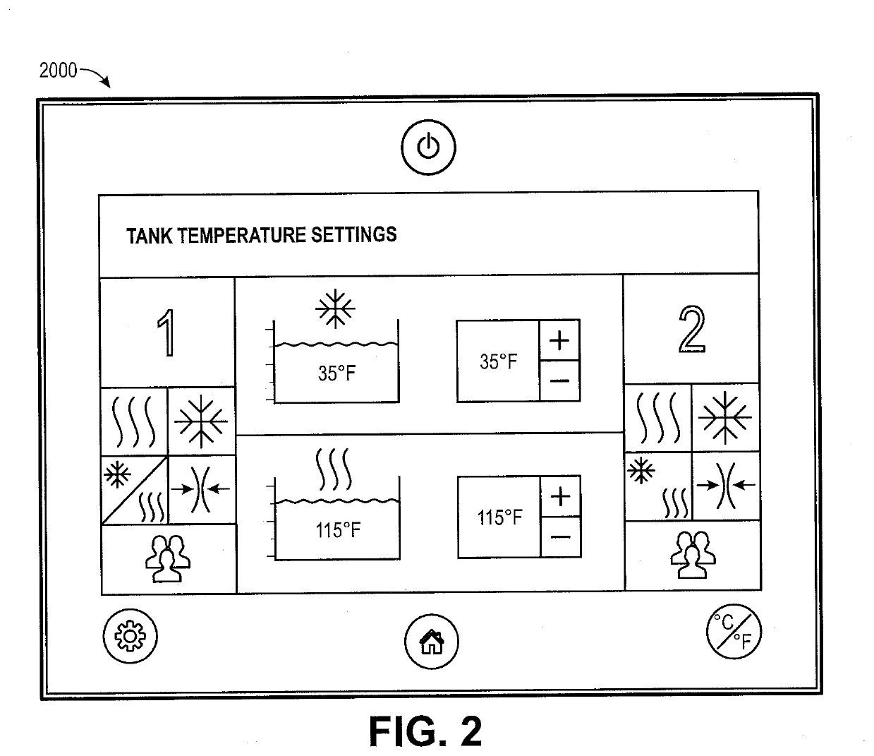
[0116]In some embodiments, the system 1000 can have a user interface 1002 on an upper front facing panel. The user i...


PUM


Abstract

A rapid contrast therapy system can provide cold, heat/hot/warm (hereafter referred to as “hot”), and/or rapid contrast therapy, which involves rapidly alternating between cold therapy and hot therapy. The system can circulate cold or hot fluid, such as water, through a hose, into a therapy wrap, and then back to the fluid reservoirs of the system. The system can utilize a vapor compression system or other chiller technology to cool the cold water reservoir, and immersion heaters can be used to heat the hot water reservoir.

Description

CROSS REFERENCE TO RELATED APPLICATIONS[0001]This application claims priority to U.S. Provisional Application No. 62 / 690,875, filed Jun. 27, 2018. This application may be related to International Application No. PCT / US2018 / 14556, filed Jan. 19, 2018, which claims priority to U.S. Provisional Application No. 62 / 448,367, filed Jan. 19, 2017, which is herein incorporated by reference in its entirety.INCORPORATION BY REFERENCE[0002]All publications and patent applications mentioned in this specification are herein incorporated by reference to the same extent as if each individual publication or patent application was specifically and individually indicated to be incorporated by reference.FIELD[0003]The present invention relates generally to thermal therapy of an animate body, and more particularly to rapid contrast therapy which alternates rapidly between cold therapy and hot therapy.BACKGROUND[0004]It is now common to apply cold and compression to a traumatized area of a human body to ...

Claims


Application Information

Patent Timeline
IPC IPC(8): A61F7/00
CPCA61F2007/0091A61F2007/0056A61F7/00A61F2007/0093A61F7/0085A61F2007/0096A61F2007/0086A61F2007/0054A61F2007/0295A61F2007/0296
Inventor LOWE, MARK H.HUFF, BRYAN
Owner AVENT INC
Why Eureka
Try Eureka