Eureka AIR delivers breakthrough ideas for toughest innovation challenges, trusted by R&D personnel around the world.

Lateral discontinuities having thicknesses increasing from shoulder to center of tire tread

Inactive Publication Date: 2020-01-02
MICHELIN & CO CIE GEN DES ESTAB MICHELIN
View PDF0 Cites 0 Cited by
  • Summary
  • Abstract
  • Description
  • Claims
  • Application Information

AI Technical Summary

Benefits of technology

This patent describes a tire tread design with longitudinally, laterally, and depthwise arranged tread elements and discontinuities that provide improved performance. The tire tread is divided into regions, with the outermost regions having a smaller thickness of the discontinuities than the centermost region. This design helps to improve tire tread wear, better traction, and reduced noise levels.

Problems solved by technology

Tread wear mostly occurs when the portion of tread in contact with a ground surface exits this contact during tire rolling operation.
With regard to altering the length of tread elements, while this may provide certain improvements for certain driving conditions, tire performance in other conditions may be negatively impacted.
As to altering the length or radius of any rib, while providing a flatter profile may improve wear consistency across the width of the tread from rib-to-rib, this flatter profile alters the shape of the tire footprint (the area of contact between the tire and the ground surface), which in turn provides a more rectangular footprint that can negatively impact other performance measures, such as noise, handling, and comfort, for example.
Therefore, there is a need to provide another mechanism for improving the wear consistency between ribs located across a tread width that does not necessarily generate reductions in other performance measures.

Method used


Image

  • Lateral discontinuities having thicknesses increasing from shoulder to center of tire tread
  • Lateral discontinuities having thicknesses increasing from shoulder to center of tire tread
  • Lateral discontinuities having thicknesses increasing from shoulder to center of tire tread

Examples


Embodiment Construction

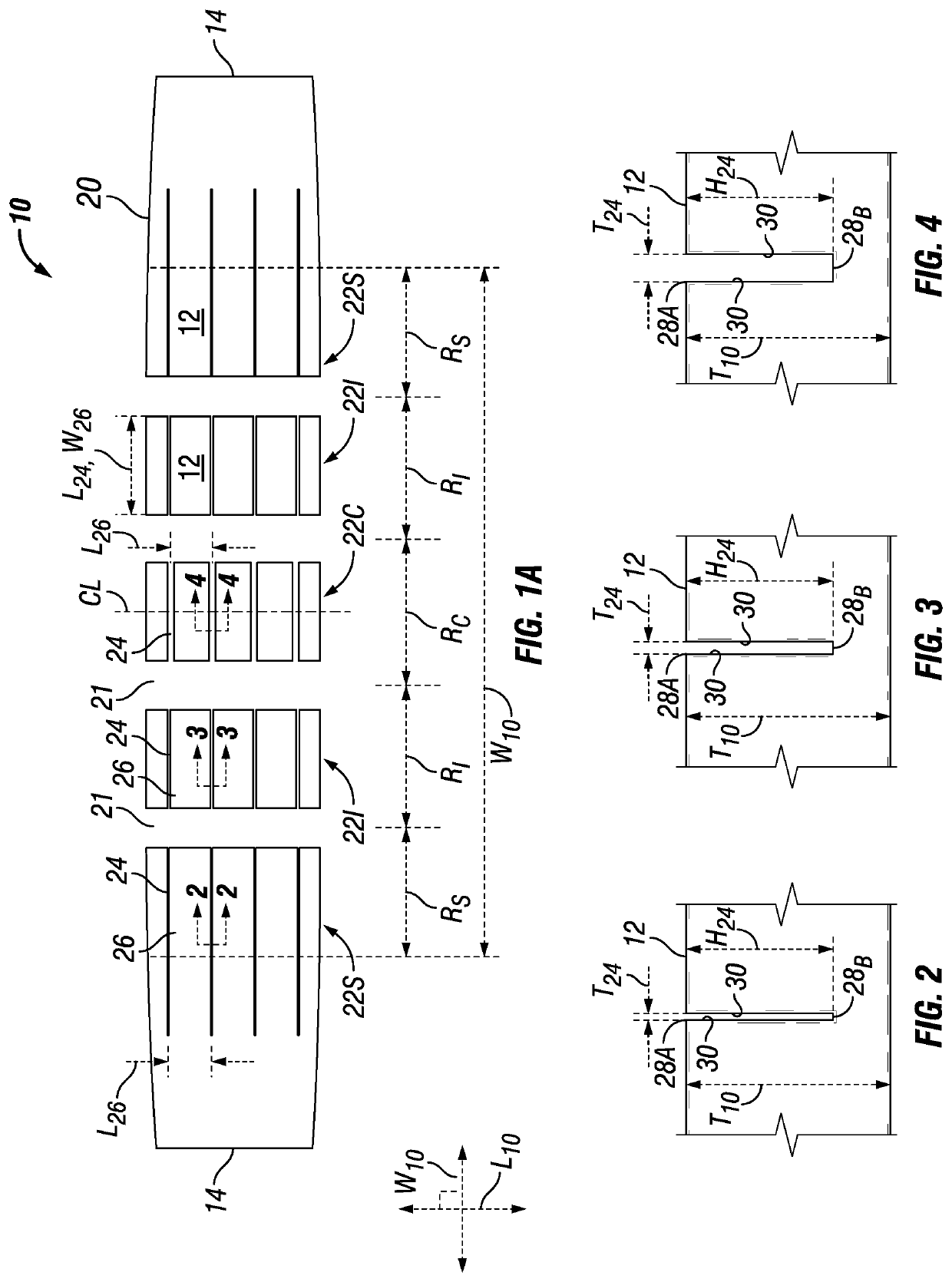
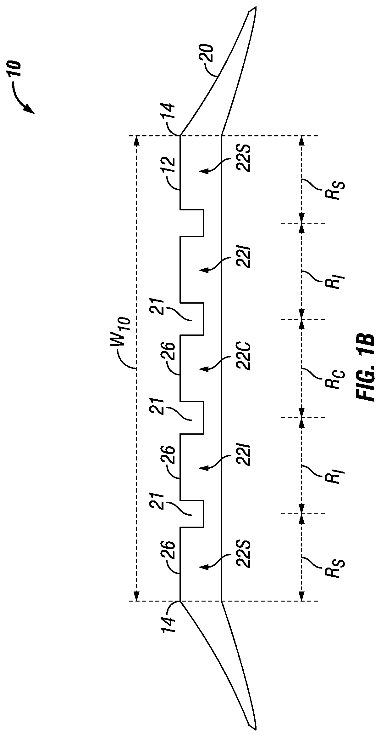
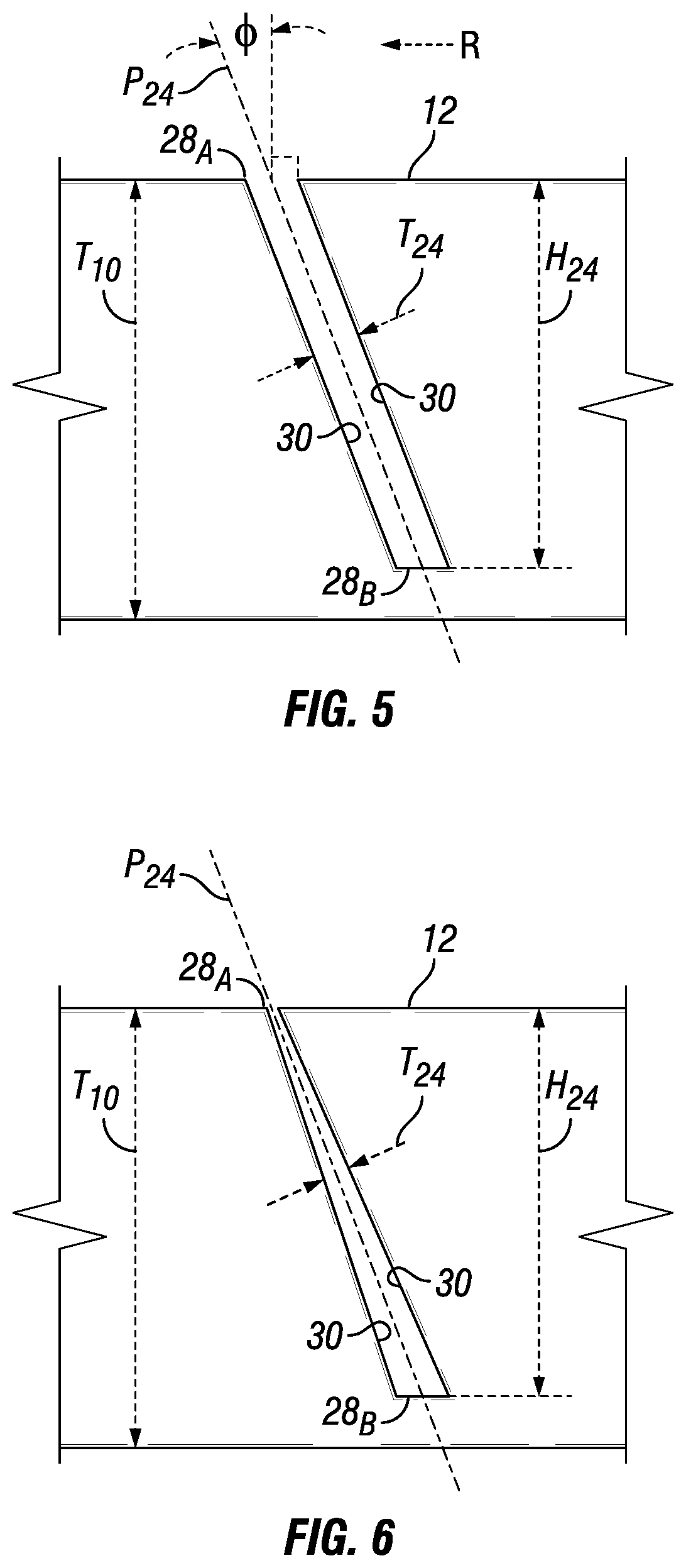
[0023]It is has been determined that by varying the thickness of any lateral discontinuity between different regions or ribs arranged at different widthwise locations across the tread, that is, by employing lateral discontinuities within a particular widthwise region or rib having a thickness different from lateral discontinuities arranged in other regions or ribs located at different lateral locations across the tread width, more consistent wear may be achieved across the tread width between the regions or ribs. Use of this new technique can be used together with any of the other techniques for managing the wear profile of a tire tread. It is especially appreciated that this new technique may be used as an alternative to the other techniques, thereby permitting improved wear profiles without sacrificing other performance measures that may arise when employing the other, prior art techniques. For example, by not flattening the lateral tread profile, the advantages of maintaining a r...


PUM


Abstract

Embodiments include a tire tread having a plurality of tread elements and a plurality of lateral discontinuities arranged along the tread width and tread length, each of the plurality of tread elements being spaced apart by one of the plurality of lateral discontinuities. The tread width is divided into a plurality of regions, the plurality of regions including: (1) a pair of outermost regions, each outermost region being arranged closest to one of the pair of opposing lateral sides of the tread, and (2) at least one centermost region is arranged closest to the longitudinal centerline of the tread. Each of the lateral discontinuities have a thickness, where the thickness of one or more of the lateral discontinuities arranged in each of the outermost regions is smaller than the thickness of one or more of the lateral discontinuities arranged in the centermost region.

Description

CROSS-REFERENCE TO RELATED APPLICATION[0001]This application claims priority to, and the benefit of, International Patent Application No. PCT / US2016 / 064268, filed Nov. 30, 2016 with the U.S. Patent Office (in the capacity of a Receiving Office), and which is hereby incorporated by reference.BACKGROUNDField[0002]This disclosure relates generally to tire treads, and more particularly, to tire treads having a plurality of tread elements with lateral discontinuities arranged there between.Description of the Related Art[0003]Tread wear mostly occurs when the portion of tread in contact with a ground surface exits this contact during tire rolling operation. This wear occurs as a result of slip occurring between the tread and the ground surface as the tread exits contact, which arises due to two phenomena acting concurrently. Particularly, this slip occurs due to the combination of maximum shear strain and a reduction of radial pressure to zero occurring at the trailing edge of tire contac...

Claims


Application Information

Patent Timeline
IPC IPC(8): B60C11/12B60C11/03B60C11/11
CPCB60C2011/0365B60C2011/1209B60C11/0302B60C11/1218B60C2011/1286B60C11/0306B60C11/1281B60C2011/1277B60C11/11B60C11/0332B60C11/04
Inventor LIMROTH, JOHNCOLLETT, MARK
Owner MICHELIN & CO CIE GEN DES ESTAB MICHELIN
Why Eureka
Eureka Blog
Learn More