Runout detection device

a detection device and runout technology, applied in measurement devices, measurement gauges, instruments, etc., can solve the problems of severe restrictions on the increase in production efficiency, and achieve the effects of low production cost, high measurement precision, and simple structur

Active Publication Date: 2020-01-02
CITIC DICASTAL
View PDF0 Cites 8 Cited by
  • Summary
  • Abstract
  • Description
  • Claims
  • Application Information

AI Technical Summary

Benefits of technology

[0004]It is an object of the present application to provide a runout detection device which may measure the runout of a seal groove in the side and the bottom of a high-pressure cast work piece.
[0008]The application may measure the runout of the sealing groove in the side and the bottom of the high-pressure cast work piece in use, and has the characteristics of high measurement precision, simple structure and low production cost.

Problems solved by technology

A runout measurement is usually made by a coordinate measuring machine (CMM), but this measurement is very inefficient thus severely restricting the increase in production efficiency.

Method used


Image

  • Runout detection device
  • Runout detection device
  • Runout detection device

Examples


Embodiment Construction

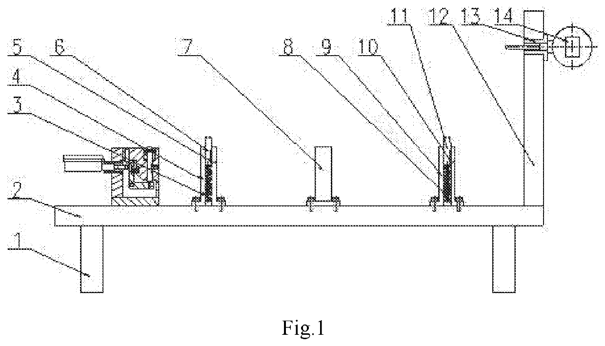
[0014]The details and operation of a specific device according to the present application will be described below with reference to the accompanying drawings.

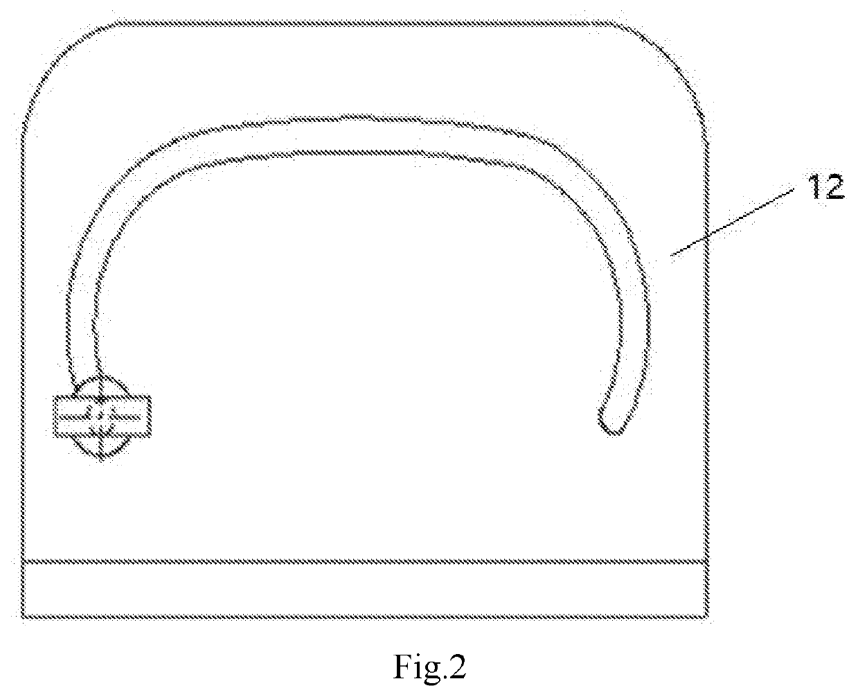
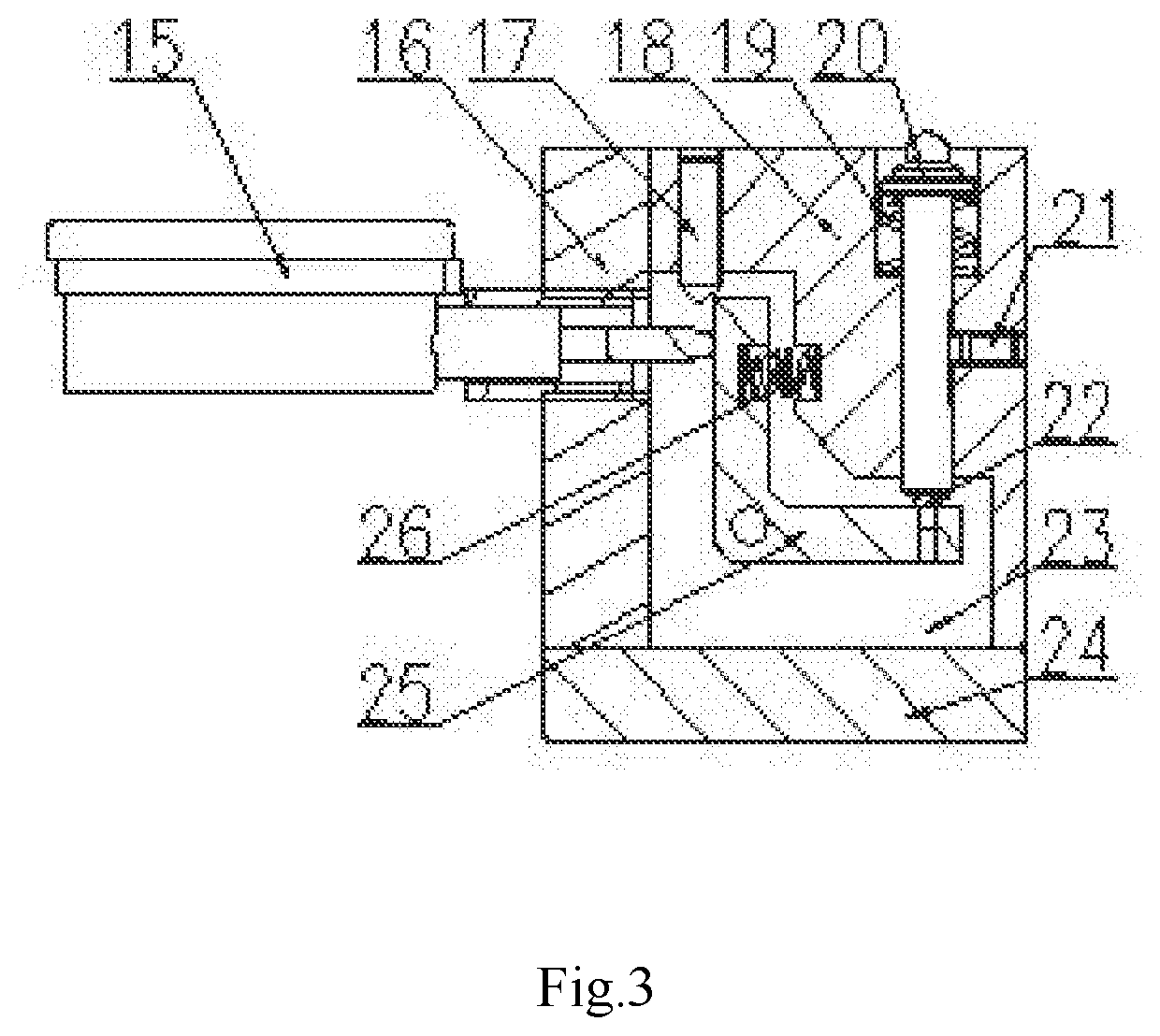
[0015]The device includes feet 1, a base plate 2, a left spring 3, a left guide sleeve 4, a left screw 5, a left guide post 6, a support column 7, a right spring 8, a right guide sleeve 9, a right screw 10, a right guide post 11, a lateral formwork 12, a sliding sleeve 13, a lateral dial gauge 14, a lower dial gauge 15, a left vertical plate 16, an upper screw 17, a fixing block 18, an upper spring 19, a probe 20, a lateral screw 21, a head nail 22, lateral vertical plates 23, a bottom plate 24, an L-shaped plate 25 and a lower spring 26. Four feet 1 are fixed at four corners below the base plate 2. The left guide sleeve 4 is fixed above the base plate 2. Upper part of the left guide post 6 is tapered, and lower part thereof is cylindrical and is matched with inner hole of the left guide sleeve 4. The left screw 5 is fixed to u...


PUM


Abstract

The present application relates to a runout detection device, which includes a base plate, lateral plates, guide sleeves, springs and dial gauges, etc. During the operation, the sliding sleeve and the lateral dial gauge are moved along the sliding groove in the lateral formwork, so that the runout of right end of the work piece may be measured. The bottom plate of the lower end measuring device is placed above the base plate, the ball at the top end of the probe is always in contact with the lower end of the work piece under the action of the upper spring, the probe is pressed down when contacting a projection, and the L-shaped plate is rotated clockwise through the head nail, at this time, the runout of the lower end of the work piece may be known by the reading of the lower dial gauge.

Description

CROSS-REFERENCE TO RELATED APPLICATIONS[0001]This application claims priority to Chinese Patent Application No. 201810736880.7 filed on Jul. 2, 2018, which is hereby incorporated by reference in its entirety.TECHNICAL FIELD[0002]The present application relates to a detection device, and more particularly to a runout detection device.BACKGROUND ART[0003]The cylinder head of an automobile is generally cast by high-pressure molding, and it is necessary to detect the runout of the depth in order to ensure the depth of the machined seal grooves in the bottom and the side. A runout measurement is usually made by a coordinate measuring machine (CMM), but this measurement is very inefficient thus severely restricting the increase in production efficiency.SUMMARY OF THE INVENTION[0004]It is an object of the present application to provide a runout detection device which may measure the runout of a seal groove in the side and the bottom of a high-pressure cast work piece.[0005]In order to achi...

Claims


Application Information

Patent Timeline
Patent Type & Authority Applications(United States)
IPC IPC(8): G01B5/18G01B3/28
CPCG01B3/28G01B5/18G01B5/0002G01B5/003G01B5/201
Inventor XUE, BOWENYUAN, HAIFENGXIAO, CHANGCUNGUO, JIANDONG
Owner CITIC DICASTAL
Why Eureka
Try Eureka