Supercharge Your Innovation With Domain-Expert AI Agents!

Reversible Cutting Edge for Agricultural Cutter

a cutting edge and rotary cutting technology, applied in the field of machines, can solve the problems of cutting edge damage, extra blades are inevitably subject to being misplaced or lost, unexpected damage or wear of the blade, etc., and achieve the effect of reducing the cost of replacing worn cutting edges and simplifying the ordering of cutting edge edges

Active Publication Date: 2020-01-09
MEYER MFG
View PDF25 Cites 0 Cited by
  • Summary
  • Abstract
  • Description
  • Claims
  • Application Information

AI Technical Summary

Benefits of technology

The present invention provides a cutting edge that can be easily replaced without needing new parts. These cutting edges can be reversed to expose new teeth, making field repair easier. The replacement parts are always with the cutting edge, which simplifies ordering and reduces the chance of losing parts. The cutting edge can be used multiple times, which saves money and simplifies maintenance.

Problems solved by technology

The cutting edges are subject to damage and accordingly it is known to allow replacement of the entire cutting edges which may be unbolted directly from the auger for replacement or which may be unbolted from a holder plate which attached to the augur.
In these locations, unexpected damage to or wear of the blades can be difficult to correct if replacement blades are not brought along or were not previously ordered.
Extra blades are inevitably subject to being misplaced or lost.

Method used


Image

  • Reversible Cutting Edge for Agricultural Cutter
  • Reversible Cutting Edge for Agricultural Cutter
  • Reversible Cutting Edge for Agricultural Cutter

Examples


Embodiment Construction

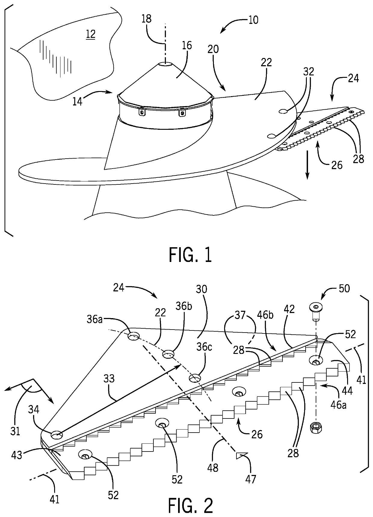
[0040]Referring now to FIG. 1, a mixer 10 may provide for a hopper 12 for receiving feed materials through an upper opening. An augur 14 may be positioned within the hopper 12 and provide an augur shaft 16 rotating about a vertical axis 18. The auger shaft 16 may be attached to a helical flute 20 providing a flute vane 22 extending radially about the axis 18 about the auger shaft 16. Generally, the augur 14 rotates so that the flute 20 draws materials up from the bottom of the hopper 12 with rotation.

[0041]Multiple augur cutters 24 may be attached to the outer edge of the flute vane 22 (only one shown) at multiple locations along the flute 20. Each auger cutter 24 extends generally horizontally from the outer edge of the flute vane 22 to expose a front edge 26 oriented with respect to rotation of the augur 14 so that the rank of cutting teeth 28 on the front edge 26 will be drawn across feed materials held within the hopper 12 during mixing.

[0042]Referring also to FIG. 2, each augur...


PUM


Abstract

A cutting edge for agricultural use provides opposed cutting edges arranged to be rotationally symmetric about an axis so that the cutting edge may be reversed in the field to repair or replace the cutting edge without the need for separate spare parts. In some embodiments a support plate may provide a ledge stop supporting the unused cutting edge to absorb impact shocks without cutting edge damage.

Description

STATEMENT REGARDING FEDERALLY SPONSORED RESEARCH OR DEVELOPMENT[0001]--CROSS REFERENCE TO RELATED APPLICATION[0002]--BACKGROUND OF THE INVENTION[0003]The present invention relates generally to machines for preparing feed for ruminant farm animals and the like and in particular to a reversible cutting edge for such that provides improved serviceability.[0004]Preparing feed for large animals such as dairy cows can be done through the use of an agricultural mixer, for example, providing a large hopper with a vertically extending augur that rotates to mix feed materials introduced into the hopper. The edge of the augur may support multiple cutting edges having serrated edges that catch and cut fibrous materials such as hay and silage during the mixing process.[0005]The cutting edges are subject to damage and accordingly it is known to allow replacement of the entire cutting edges which may be unbolted directly from the auger for replacement or which may be unbolted from a holder plate w...

Claims


Application Information

Patent Timeline
Patent Type & Authority Applications(United States)
IPC IPC(8): B01F7/00A01K5/00B01F15/02B02C18/18
CPCA01K5/001B01F7/00416B01F2215/0008B01F7/00616B02C18/18B01F15/0235B01F27/172B01F27/92A01K5/004B01F27/1143B01F35/71731B01F2101/18
Inventor REPKA, JOSEPH MICHAELALBRIGHT, CHRISTOPHER J.
Owner MEYER MFG
Features
  • R&D
  • Intellectual Property
  • Life Sciences
  • Materials
  • Tech Scout
  • Unparalleled Data Quality
  • Higher Quality Content
  • 60% Fewer Hallucinations
Learn More