
Tire

a technology of tires and grooves, applied in the field of tires, can solve the problems of reducing the efficiency of cleaning the vulcanization mold, the inability to easily apply laser, particles, or the like used for molding surface cleaning, and the inability to easily apply into the groove portions, so as to prevent the number of ridges in the circumferential direction of the tire from increasing excessively, the effect of reducing the proportion of the groove portions

Active Publication Date: 2020-01-16
SUMITOMO RUBBER IND LTD
View PDF3 Cites 1 Cited by
  • Summary
  • Abstract
  • Description
  • Claims
  • Application Information

AI Technical Summary

Benefits of technology

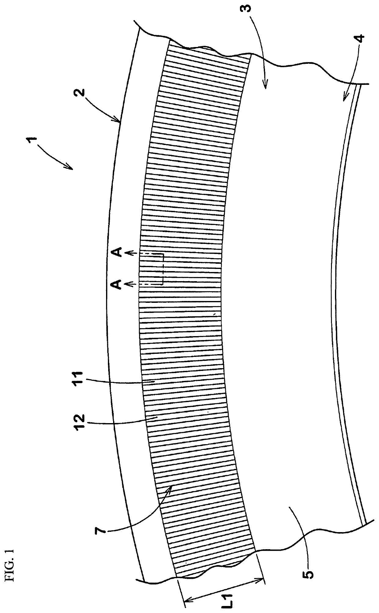
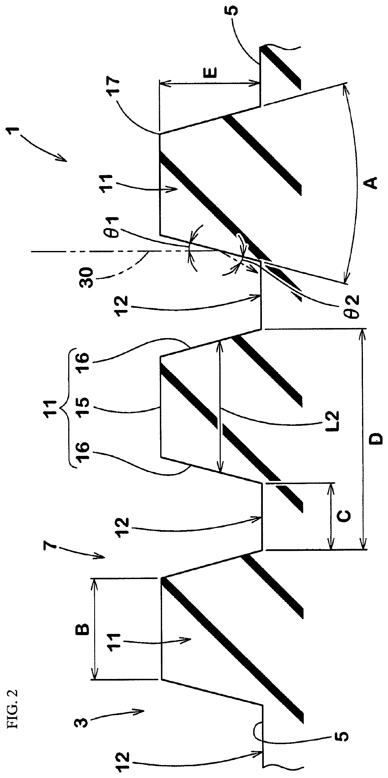
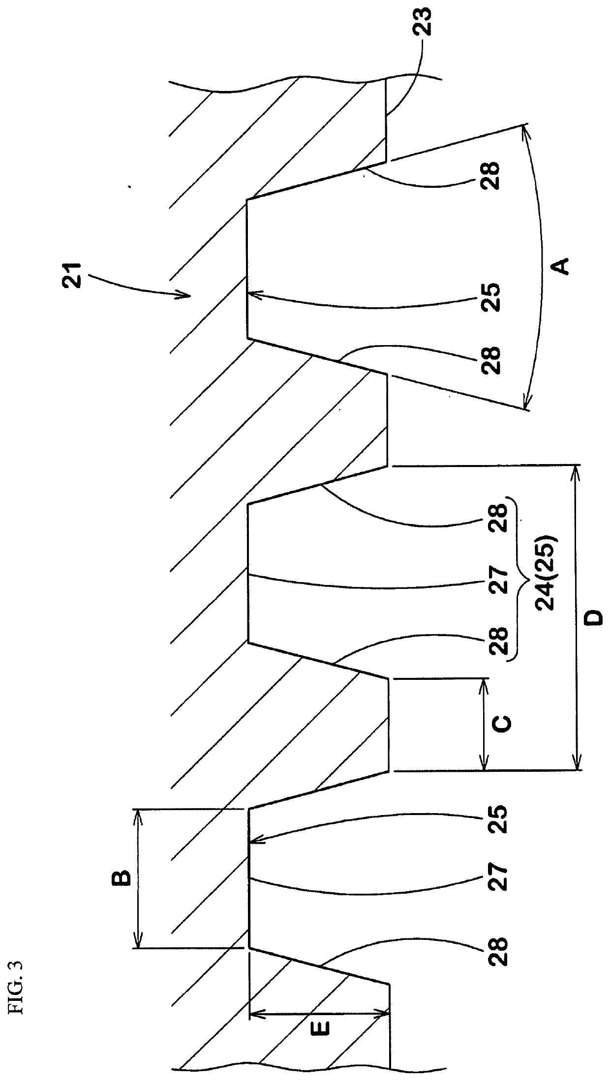
The present invention provides a tire with improved outer appearance and efficiency for cleaning a vulcanization mold. The tire has a decorative pattern on its sidewall portion with multiple ridges that align in a circle to form gaps. The decorative pattern prevents recesses and projections from becoming conspicuous and improves the tire's appearance. Additionally, the decorative pattern allows for improved cleaning of the mold by facilitating the application of laser, particles, or other cleaning methods. The pattern is formed with ridges that have a taper angle not greater than 40 degrees and a minimum length for the gap of not greater than 0.25 mm to further inhibit the appearance of recesses and projections. The decorative pattern also ensures that the groove portion of the mold is appropriately expanded for efficient cleaning and prevents excessive increases in the number of ridges in the tire circumferential direction.

Problems solved by technology

Laser, particles, or the like used for cleaning the molding surface are unlikely to be easily applied into the groove portions.
Therefore, a problem arises that efficiency for cleaning the vulcanization mold is reduced.

Method used


Image

  • Tire
  • Tire
  • Tire

Examples


examples

[0068]Tires (size: 195 / 65R15) were produced as sample tires according to specifications indicated in Table 1 such that the decorative patterns were formed on surfaces of the sidewall portions (examples 1 to 10 and comparative examples 1 to 12). The tires of examples and comparative examples were each evaluated for processability for the pattern forming portion (groove) of the vulcanization mold, cost for processing the pattern forming portion of the vulcanization mold, outer appearance of the tire, performance of hiding recesses and projections, efficiency for cleaning the vulcanization mold, and outer appearance of the tire after the pattern forming portion of the vulcanization mold was worn. The evaluation methods are as follows.

[0069]

[0070]A time and cost required for processing the pattern forming portion (groove) of the vulcanization mold, in the molding surface of the vulcanization mold, were obtained. The evaluation is indicated as an index with the index of example 2 being 1...


PUM

PropertyMeasurementUnit
lengthaaaaaaaaaa
heightaaaaaaaaaa
lengthaaaaaaaaaa

Abstract

A tire that includes a decorative pattern formed on a surface of a sidewall portion. The decorative pattern is formed such that a plurality of ridges that extend in a tire radial direction are aligned in a tire circumferential direction so as to form gaps. A transverse cross-section of each ridge is tapered so as to gradually reduce a length along the surface such that the greater a distance from the surface is, the less the length along the surface is. The decorative pattern is structured so as to satisfy expressions (1) and (2):20≤A≤40  (1)0.15≤C≤0.25  (2)wherein A represents a taper angle (degree) of the ridge, and C represents a minimum length (mm) of each gap measured along the surface.

Description

BACKGROUND OF THE INVENTIONField of the Invention[0001]The present invention relates to a tire having a decorative pattern formed on a surface of a sidewall portion.Description of the Background Art[0002]In general, a sidewall portion of a tire has thin rubber, and, therefore, recesses and projections called dents and bulges become conspicuous due to, for example, residual air and a joint portion of a carcass that is an internal structure. Such recesses and projections deteriorate outer appearance of the tire.[0003]Japanese Laid-Open Patent Publication No. 7-164831 suggests a tire which has a strip-like design in which multiple ridges are disposed on a surface of a sidewall at a predetermined pitch such that the recesses and projections are unlikely to become conspicuous. Such a strip-like design is formed by groove portions (reversed pattern of the ridges) formed in a molding surface of a vulcanization mold for the tire.SUMMARY OF THE INVENTION[0004]In order to make the recesses an...

Claims


Application Information

Patent Timeline
Patent Type & Authority Applications(United States)
IPC IPC(8): B60C13/00B60C13/02B29D30/72B29D30/06
CPCB29D2030/726B29D30/0606B60C13/001B60C13/02B29D30/72B29D2030/0612B60C13/00B29D2030/0616
Inventor OGIHARA, SAWA
Owner SUMITOMO RUBBER IND LTD
Learn More