Array camera module having height difference, circuit board assembly and manufacturing method therefor, and electronic device

a technology of array camera and height difference, which is applied in the field of array camera module, to achieve the effect of compactness and reducing the space occupied by electronic elements

Active Publication Date: 2020-01-16
NINGBO SUNNY OPOTECH CO LTD
View PDF0 Cites 19 Cited by
  • Summary
  • Abstract
  • Description
  • Claims
  • Application Information

AI Technical Summary

Benefits of technology

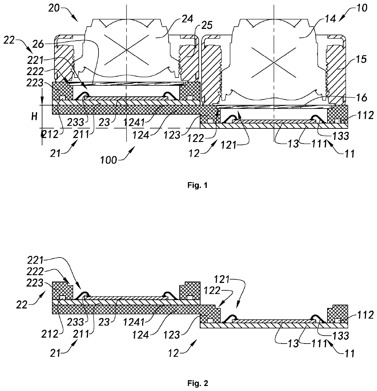
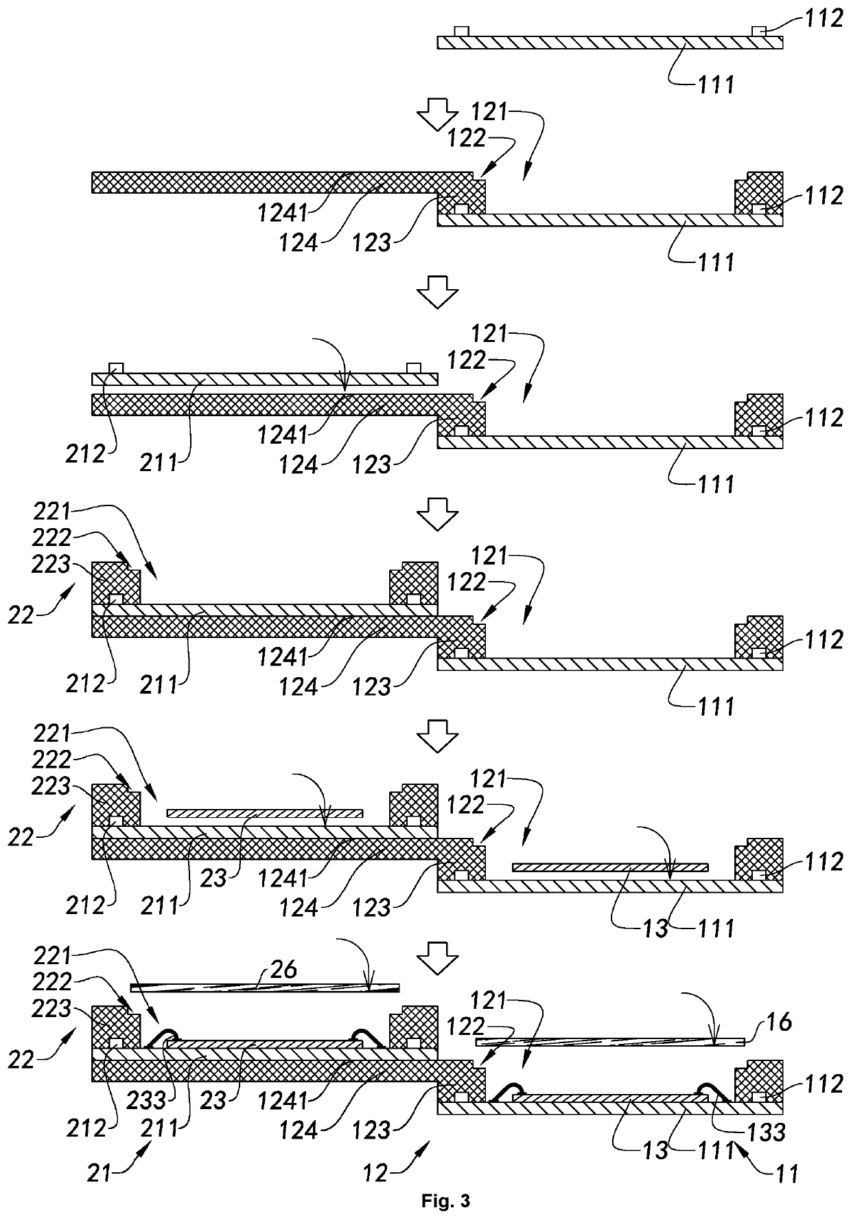
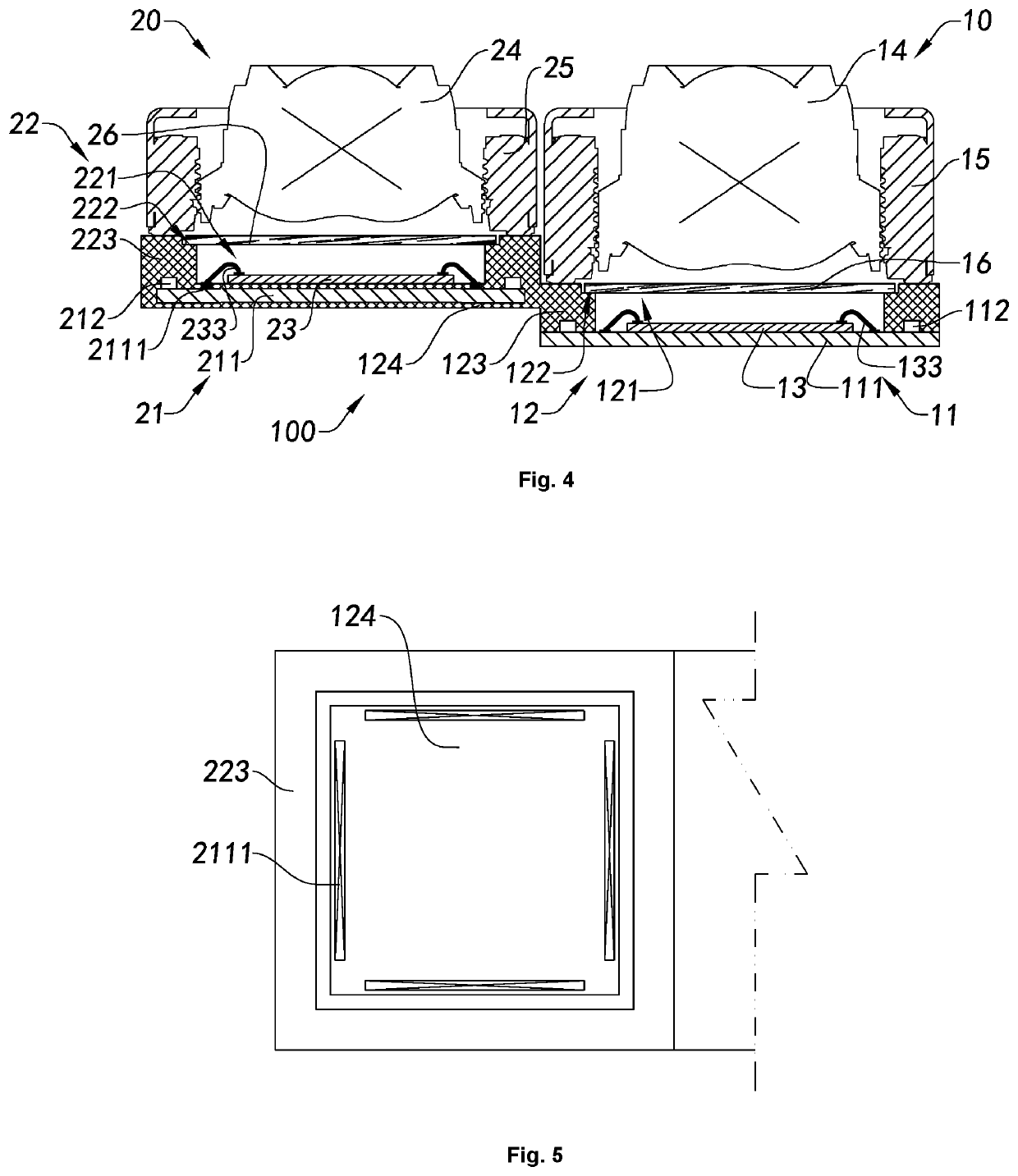
[0024]An object of the present invention is to provide an array camera module having a height difference, a circuit board assembly and a manufacturing method therefor, and an electronic device, wherein the circuit board assembly comprises a circuit board body and at least one electronic element, and the first base covers the electronic element, thereby reducing the space occupied by the electronic element, so that the array camera module is more compact.

Problems solved by technology

However, no matter which function the dual camera has, it needs hardware support, and need to consider a most basic issue, i.e. the assembly fixing issue between the two cameras.
How to assemble the two cameras stably and compactly into an integral module is a basic issue considered for the dual camera module.
Such a requirement for different functions usually causes the two cameras to have different sizes, such as different heights, and how to stably combine the two cameras of different heights into an integral module is another important issue encountered in the development of the dual camera module.
That is, another important issue that need to be considered for the development of the dual cameras is, on the basis of stably and compactly fixing two cameras, how to improve the consistency of the optical axes between the two camera modules or to make their error within a predetermined range, for improving the precision of the installation and making them have better image quality.

Method used


Image

  • Array camera module having height difference, circuit board assembly and manufacturing method therefor, and electronic device
  • Array camera module having height difference, circuit board assembly and manufacturing method therefor, and electronic device
  • Array camera module having height difference, circuit board assembly and manufacturing method therefor, and electronic device

Examples


Embodiment Construction

[0199]The following description is presented to disclose the present invention to enable those skilled in the art to practice the present invention. The preferred embodiments in the following description are by way of example only, and other obvious modifications will occur to those skilled in the art. The basic principles of the present invention as defined in the following description may be applied to other embodiments, modifications, improvements, equivalents, and other technical solutions without departing from the spirit and scope of the present invention.

[0200]It will be understood by those skilled in the art that in the disclosure of the present invention, the orientation or positional relationship indicated by the terms “longitudinal”, “transverse”, “upper”, “lower”, “front”, “back”, “left”, “right”, ““upright”, “horizontal”, “top”, “bottom”, “inside”, “outside”, etc. is based on the orientation or positional relationship shown in the figures, which is merely for convenienc...


PUM


Abstract

An array camera module having a height difference, a circuit board assembly and a manufacturing method therefor, and an electronic device. The array camera module comprises a first camera module unit and a second camera module unit, wherein the first camera module unit comprises at least one first photosensitive assembly and at least one first lens; the first lens is located on a photosensitive path of the first photosensitive assembly; the first photosensitive assembly comprises at least one extension portion; the extension portion at least partially extends towards the direction away from the first photosensitive assembly; and the second camera module unit is fixedly connected to a second extension portion, so that the ends of the two camera module units are consistent.

Description

TECHNICAL FIELD[0001]The present invention relates to the field of camera modules, and further relates to an array camera module having a height difference, a circuit board assembly and a manufacturing method therefor, and an electronic device.TECHNICAL BACKGROUND[0002]With the continuous development of smart devices, the requirements for camera modules are increasing. For example, in the past two years, a smart phone camera has changed from a single camera to a dual camera, and the development of the dual camera module has become an important trend in the development of mobile phone camera modules.[0003]Simply speaking, the dual camera can acquire images with the cooperation of two cameras, enabling a more versatile and powerful image acquisition function. The existing dual cameras can be divided into two types according to their functions: one of which is to use two cameras to generate stereo vision, obtain the depth of field of an image, and use the depth of field information for...

Claims


Application Information

Patent Timeline
Patent Type & Authority Applications(United States)
IPC IPC(8): H04N5/225H04N5/247
CPCH04N5/2254H04N5/247H04N5/2253H04N23/50H04N23/00H04N23/57H04N23/55H04M1/0264H04N23/54H04N23/45G03B17/12H04N23/90
Inventor WANG, MINGZHUTANAKA, TAKEHIKOCHEN, ZHENYUGUO, NANZHAO, BOJIEMEI, ZHEWEN
Owner NINGBO SUNNY OPOTECH CO LTD
Why Eureka
Try Eureka