Eureka AIR delivers breakthrough ideas for toughest innovation challenges, trusted by R&D personnel around the world.

Gas turbine engine

Inactive Publication Date: 2020-01-23
ROLLS ROYCE PLC
View PDF0 Cites 0 Cited by
  • Summary
  • Abstract
  • Description
  • Claims
  • Application Information

AI Technical Summary

Benefits of technology

The present patent relates to a gas turbine engine for aircraft that includes an engine core and a covering. The engine accessory interacts with the engine core or a component of the engine core. The covering can be a socket that the engine accessory is connected to. The engine accessory can be a removable connection or a fixed connection. The engine accessory can be a continuous surface that forms a part of the covering. The covering can also have a channel that connects the engine accessory to the engine core. The gas turbine engine can also have a fan located upstream of the engine core. The engine core can have one or more shafts that connect turbines and compressors. The engine accessory can be a fan that is driven by a gearbox. The technical effects of this patent include improved performance, efficiency, and durability of gas turbine engines for aircraft.

Problems solved by technology

It would be advantageous to make the core fairings structural to stiffen and support the engine core, but this is difficult to achieve if the core fairings are designed to be opened regularly.

Method used


Image

  • Gas turbine engine
  • Gas turbine engine
  • Gas turbine engine

Examples


Embodiment Construction

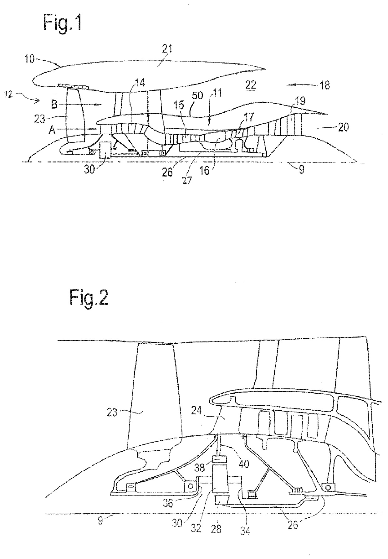
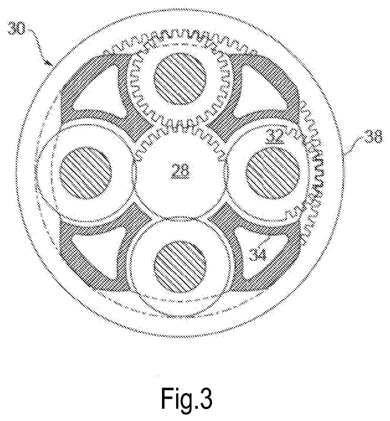
[0057]FIG. 1 illustrates a gas turbine engine 10 having a principal rotational axis 9. The engine 10 comprises an air intake 12 and a propulsive fan 23 that generates two airflows: a core airflow A and a bypass airflow B. The gas turbine engine 10 comprises a core 11 that receives the core airflow A. The engine core 11 comprises, in axial flow series, a low pressure compressor 14, a high-pressure compressor 15, combustion equipment 16, a high-pressure turbine 17, a low pressure turbine 19 and a core exhaust nozzle 20. A nacelle 21 surrounds the gas turbine engine 10 and defines a bypass duct 22 and a bypass exhaust nozzle 18. The bypass airflow B flows through the bypass duct 22. The fan 23 is attached to and driven by the low pressure turbine 19 via a shaft 26 and an epicyclic gearbox 30.

[0058]In use, the core airflow A is accelerated and compressed by the low pressure compressor 14 and directed into the high pressure compressor 15 where further compression takes place. The compres...


PUM


Abstract

A gas turbine engine for an aircraft, comprising: an engine core; a covering configured to cover at least part of the engine core; and an engine accessory that interacts with the engine core or a component of the engine core; wherein the engine accessory is outside the covering.

Description

CROSS REFERENCE TO RELATED APPLICATIONS[0001]This application is based upon and claims the benefit of priority from UK Patent Application No. GB 1806461.8, filed on 20 Apr. 2018, the entire contents of which are herein incorporated by reference.BACKGROUNDTechnical Field[0002]The present disclosure relates to gas turbine engines, in particular gas turbine engines comprising an engine accessory that interacts with an engine core or a component of the engine core.Description of the Related Art[0003]Gas turbine engines are typically provided with coverings, also known as casings or core fairings, around the engine core to improve the aerodynamic profile of the engine core within the engine structure. The core fairings are typically non-structural and may be opened to provide access to units mounted on the core structure. It would be advantageous to make the core fairings structural to stiffen and support the engine core, but this is difficult to achieve if the core fairings are designed...

Claims


Application Information

Patent Timeline
IPC IPC(8): F02C7/32F02C3/04F02C7/36F02C7/20
CPCF02C7/36F05D2230/70F02C7/32F02C7/20F05D2230/60F05D2220/32F05D2240/90F02C3/04F05D2230/72F02C6/08F02C7/18F02C7/185F02C9/18F02K3/115F05D2260/213Y02T50/60
Inventor SCOTHERN, DAVID P.
Owner ROLLS ROYCE PLC
Why Eureka
Eureka Blog
Learn More