Unlock instant, AI-driven research and patent intelligence for your innovation.

Spring structure with sliding element

a technology of sliding element and spring, which is applied in the functional characteristics of springs/dampers, machines/engines, liquid fuel engines, etc., can solve the problems of failure of springs or other internal components of pumps, and current stand designs fail to adequately prevent spring buckling

Inactive Publication Date: 2020-01-30
GM GLOBAL TECH OPERATIONS LLC
View PDF3 Cites 0 Cited by
  • Summary
  • Abstract
  • Description
  • Claims
  • Application Information

AI Technical Summary

Benefits of technology

The patent text is about an oil pump that can change the amount of oil it dispenses by moving a part called the slide. This slide can be moved by a rotating ring or a slide within the pump. The pump can change displacement by adjusting the position of the slide, which affects the eccentricity of the pump rotor. The slide is usually pushed in one direction by a spring and can be pivoted to different positions to change the displacement of the pump.

Problems solved by technology

Contact between the spring and stand may cause wear to the spring and / or stand, which may contaminate the oil and, in some cases, lead to failure of the spring or other internal components of the pump.
Moreover, current stand designs fail to adequately prevent buckling of the spring, especially if the spring is relatively elongated.

Method used


Image

  • Spring structure with sliding element
  • Spring structure with sliding element

Examples


Embodiment Construction

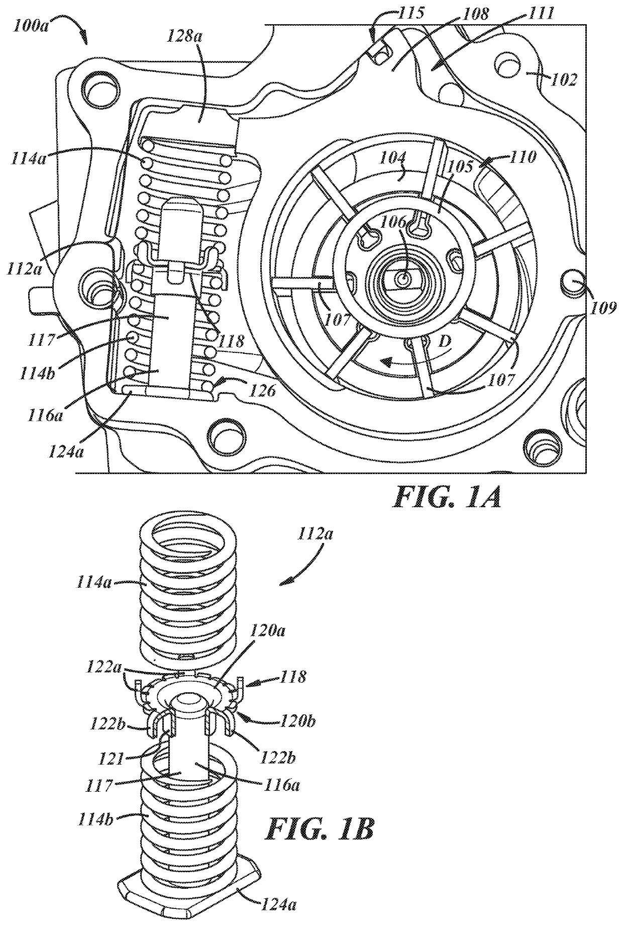
[0021]Exemplary systems and methods are provided herein for a biasing assembly for a pump, such as a variable displacement pump. Example biasing assemblies may provide support to one or more biasing elements, e.g., springs, coil springs, flexible bellows, or any other resilient element capable of providing a spring force. As will be described further below, example biasing assemblies may provide lateral support to one or more longitudinally extending resilient elements by way of a sliding support, thereby increasing durability of the biasing assemblies. A pump employing an example biasing assembly may thereby be provided with improved durability and reduced overall weight amongst other advantages, which will be described further below.

[0022]Turning now to FIGS. 1A, 1B and 1C, an example variable displacement pump 100a is illustrated. The pump 100a may include a housing 102 having an inlet and an outlet (not shown in FIG. 1A). The pump 100a may further include a rotor 104 that is fix...


PUM


Abstract

Variable displacement pumps and biasing assemblies for the same are disclosed. Example pumps may include a housing having an inlet and an outlet, and a rotor fixed for rotation with a shaft, with the shaft rotatably mounted within the housing. The pump may further include a plurality of radially extending vanes slidably disposed in the rotor, and a pivotable ring member defining a control chamber about the rotor, with the ring member being pivotable within the housing to vary an eccentricity of the ring member with respect to the rotor. The pump may further include a biasing assembly applying a biasing force to the ring member in a first direction about the shaft, with the biasing assembly including at least one resilient element extending longitudinally along a stand, and a sliding support slidably disposed on the stand and laterally supporting the resilient element with respect to the stand.

Description

INTRODUCTION[0001]Variable displacement oil pumps may employ a rotatable ring member or slide within a housing, which facilitates a change in pump displacement by way of varying an eccentricity of the slide with respect to a pump rotor. The pivotable slide may be biased in a given direction about the axis of the rotor with a spring. The slide may be pivoted to a desired position corresponding to a desired displacement of the pump.[0002]Known biasing elements employ a spring mounted on a stand, which aligns the spring between the slide and the housing. The stand typically contacts the spring periodically during use, especially where the spring is relatively elongated. Contact between the spring and stand may cause wear to the spring and / or stand, which may contaminate the oil and, in some cases, lead to failure of the spring or other internal components of the pump. The expected contact between the spring and stand, both of which are typically formed of a metal material, also imposes...

Claims


Application Information

Patent Timeline
IPC IPC(8): F04C14/22F04C2/344F16F1/12
CPCF01M2001/0238F04C14/22F04C2/3442F01M1/02F16F1/12F01M1/16F01M2001/0246F04C14/226F04C2240/80F16F1/122F16F1/125F16F3/04F16F2228/06F16N13/20
Inventor BENNETT, SR., ANDYANZALONE, ANTHONYPRYOR, BRYAN K.
Owner GM GLOBAL TECH OPERATIONS LLC