X-ray transmission inspection apparatus and x-ray transmission inspection method

Active Publication Date: 2020-02-06
HITACHI HIGH TECH SCI CORP
View PDF0 Cites 0 Cited by
  • Summary
  • Abstract
  • Description
  • Claims
  • Application Information

AI Technical Summary

Benefits of technology

The present invention relates to an X-ray transmission inspection apparatus and method for inspecting a sample. The apparatus and method create a cross-sectional image of the sample by adding the images of pixels arranged in the direction the sample moves at an interval. The image is taken at a position with a distance of L from the X-ray source. By doing so, a three-dimensional X-ray image of the sample can be obtained through a single scan operation. The apparatus and method can be used for an X-ray CT scan to quickly acquire cross-sectional images of a sample at various heights.

Problems solved by technology

Thus, there was an inconvenience that it is impossible to see the internal structures of the whole body of the sample.
Therefore, it takes much time to obtain a tomogram (cross-sectional images at various heights).

Method used


Image

  • X-ray transmission inspection apparatus and x-ray transmission inspection method
  • X-ray transmission inspection apparatus and x-ray transmission inspection method
  • X-ray transmission inspection apparatus and x-ray transmission inspection method

Examples


first embodiment

[0027]Hereinafter, an X-ray transmission inspection apparatus and an X-ray transmission inspection method according to the present invention will be described with reference to FIGS. 1 through 3.

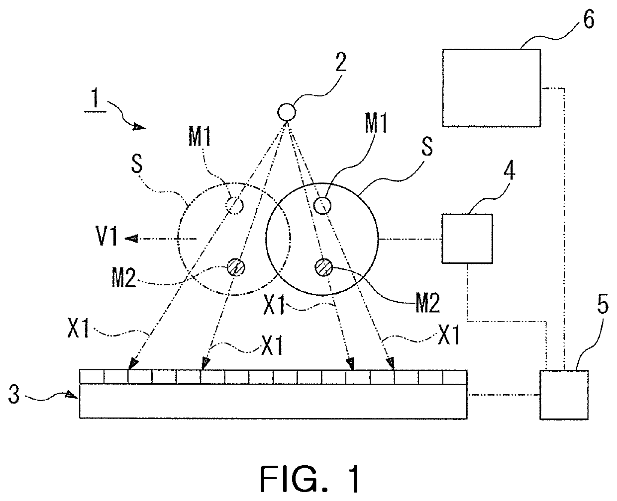
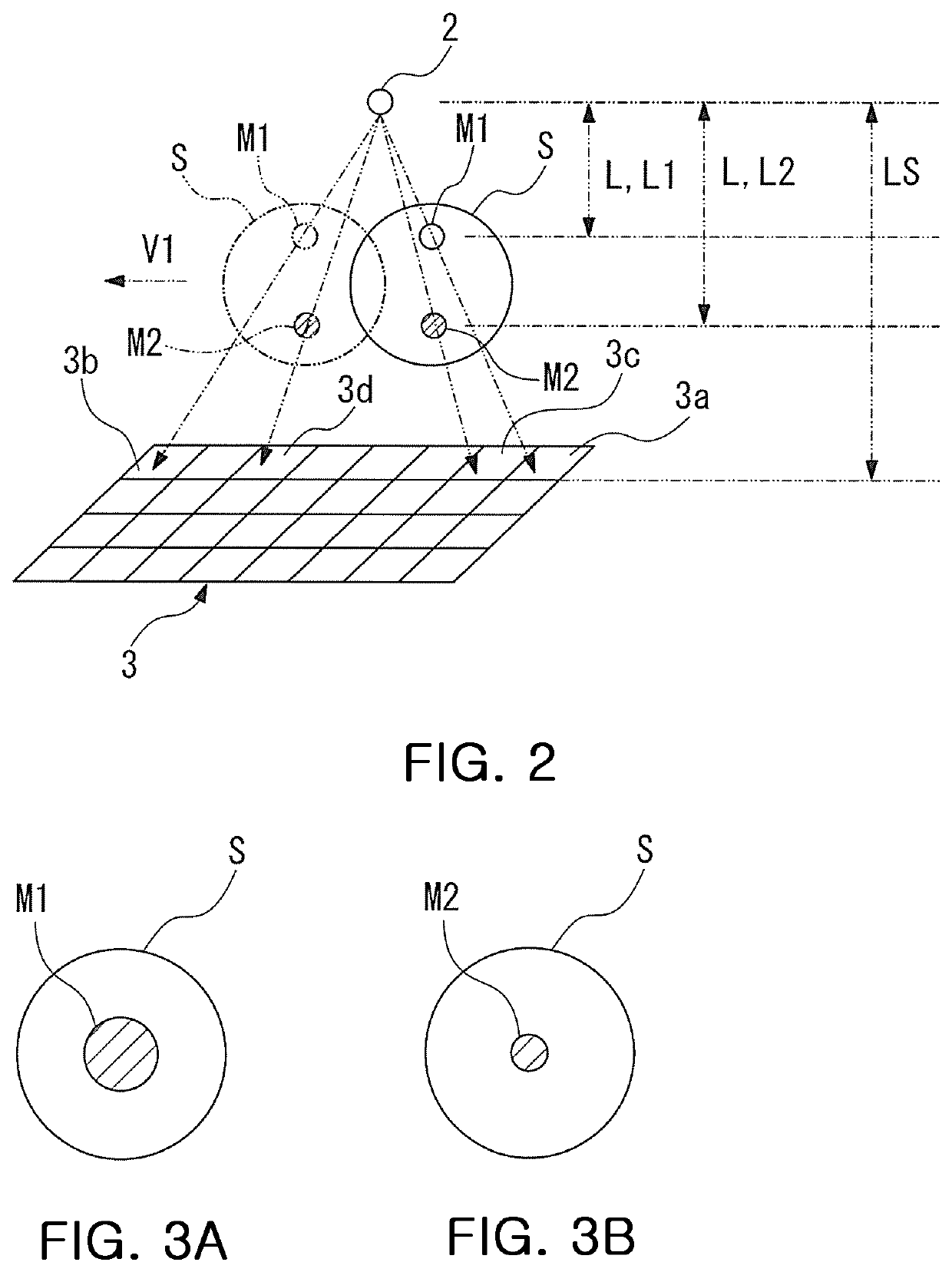
[0028]As illustrated in FIG. 1, an X-ray transmission inspection apparatus 1 according to a first embodiment of the present embodiment includes an X-ray source 2 for irradiating a sample S with X-rays X1, a two-dimensional sensor 3 installed on the opposite side of the X-ray source 2 with the sample placed therebetween and configured to detect transmission X-rays X1 passing through the sample S, a sample moving mechanism 4 for moving the sample S at a predetermined speed in a predetermined direction parallel to a detection surface of the two-dimensional sensor 3, a calculation unit 5 for processing an image of the transmission X-rays X1 detected by the two-dimensional sensor 3, and a display unit 6 for displaying a cross-sectional image generated through the image processing of the calculati...

second embodiment

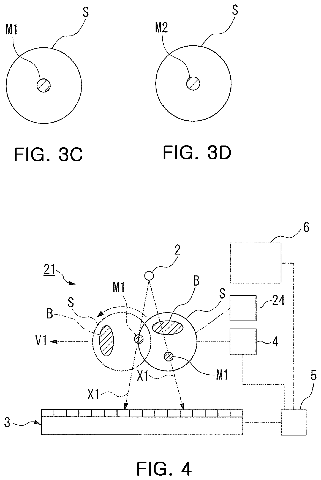
[0055] a calculation unit 5 has a function of creating multiple cross-sectional images of the sample S from measurements of X-rays X1 transmitted through the sample S which is irradiated from different directions by changing the orientation of the sample S multiple times using the sample rotating mechanism 24.

[0056]The sample rotating mechanism 24 includes, for example, a stepping motor and the like. The sample rotating mechanism 24 changes the orientation of the sample S so as to be perpendicular to the direction in which the sample S moves or tilts the sample S by a predetermined angle with respect to an axis parallel to the detection surface of a two-dimensional sensor 3.

[0057]For example, as illustrated in FIG. 4, when an X-ray shielding object B having a relatively large size exists in the sample S and a foreign object M1 is located immediately beneath the X-ray shielding object B, it is difficult to detect the foreign object M1 through a single scan because the foreign object ...


PUM


Abstract

An X-ray transmission inspection apparatus includes an X-ray source for irradiating a sample with X-rays, a two-dimensional sensor for detecting transmission X-rays passing through the sample, a sample moving mechanism for moving the sample, a calculation unit for processing an image of the transmission X-rays detected by the two-dimensional sensor, and a display unit for displaying a cross-sectional image. When V1 is a speed at which the sample moves, F is a frame rate of the two-dimensional sensor, A is a sample pitch of the two-dimensional sensor, and LS is a distance between the X-ray source and the two-dimensional sensor, the calculation unit creates a cross-sectional image taken at a distance L from the X-ray source by adding the images of the pixels positioned at an interval of [(LS×V2) / (L×F×A)] in a direction in which the sample moves.

Description

CROSS REFERENCE TO RELATED APPLICATION(S)[0001]This application claims the benefit of Japanese Patent Application No. 2018-146481, filed Aug. 3, 2018, which is hereby incorporated by reference in its entirety into this application.BACKGROUND OF THE INVENTION1. Technical Field[0002]The present invention relates to an X-ray transmission inspection apparatus and method capable of detecting foreign object such as a metallic particle in a sample.2. Description of the Related Art[0003]Generally, to detect foreign object such as a minute metal particle, in a sample, X-ray transmission inspection is carried out in which an X-ray transmission image obtained by irradiating a sample with X-rays is used.[0004]For example, Patent Document 1 discloses a transmission X-ray analysis apparatus and method capable of measuring transmission X-rays passing through a sample using a time delay integration (TDI) sensor.[0005]The transmission X-ray analysis apparatus detects a transmission X-ray image of a ...

Claims


Application Information

Patent Timeline
IPC IPC(8): G01N23/046G01N23/083G01N23/18
CPCG01N23/083G01N23/046G01N2223/3306G01N23/18G01N23/044G01N2223/3308G01N2223/1016G01N2223/652G01N23/04G01N2223/03G01N2223/401G01N23/06G01N23/087
Inventor MATOBA, YOSHIKI
Owner HITACHI HIGH TECH SCI CORP
Why Eureka
Try Eureka