Door sill assembly for a door

a technology for doors and windows, applied in the direction of doors/windows, special doors/window arrangements, doors/windows, etc., can solve the problems of difficult removal of old thresholds, cumbersome procedures, and time-consuming

a technology for doors and windows, applied in the direction of doors/windows, special doors/window arrangements, doors/windows, etc., can solve the problems of difficult removal of old thresholds, cumbersome procedures, and time-consuming

US20200048954A1Active Publication Date: 2020-02-13NANYA PLASTICS CORP

Image

  • Door sill assembly for a door
  • Door sill assembly for a door
  • Door sill assembly for a door

Examples


Embodiment Construction

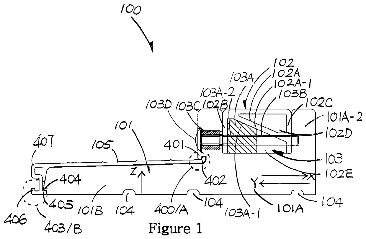
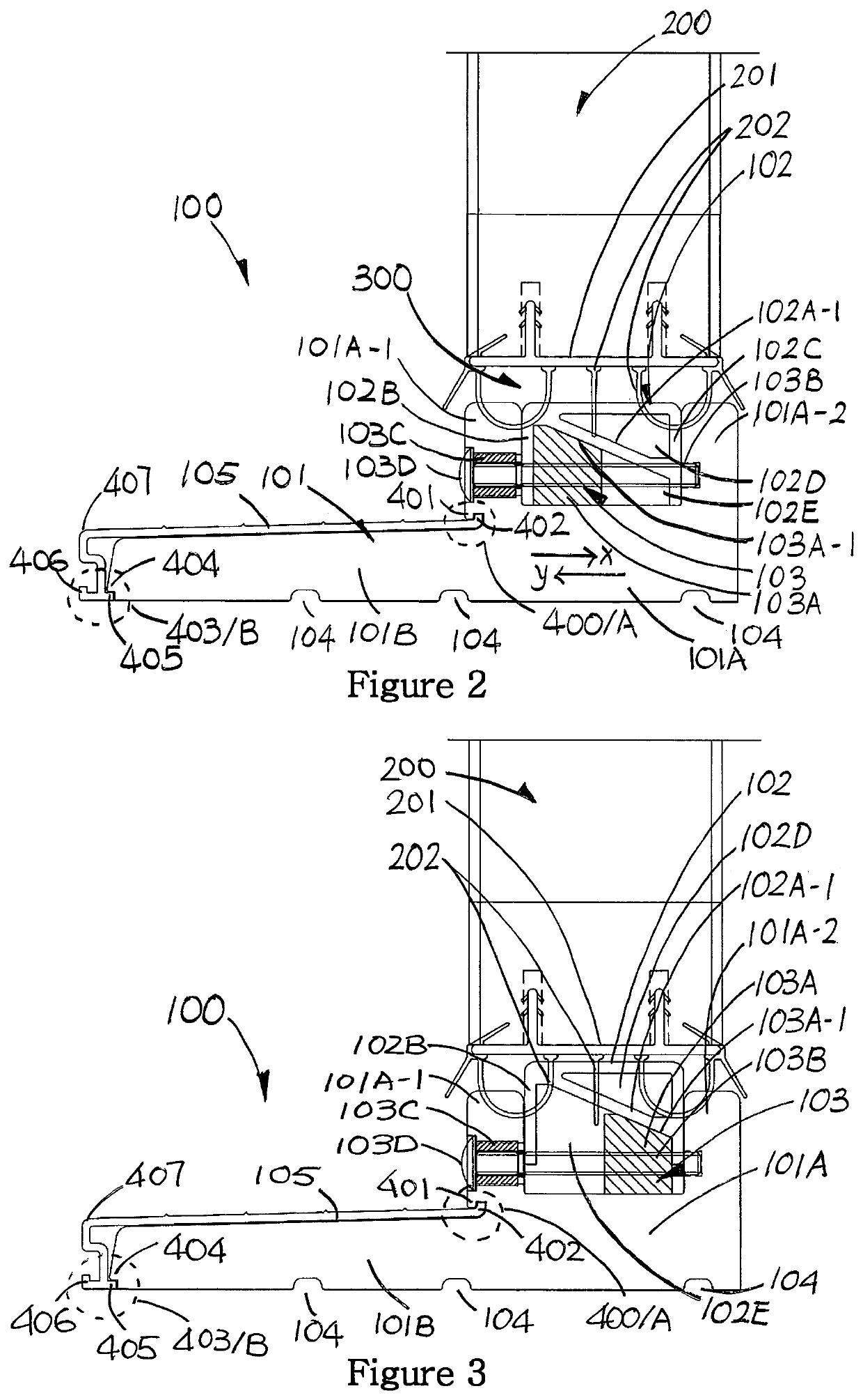
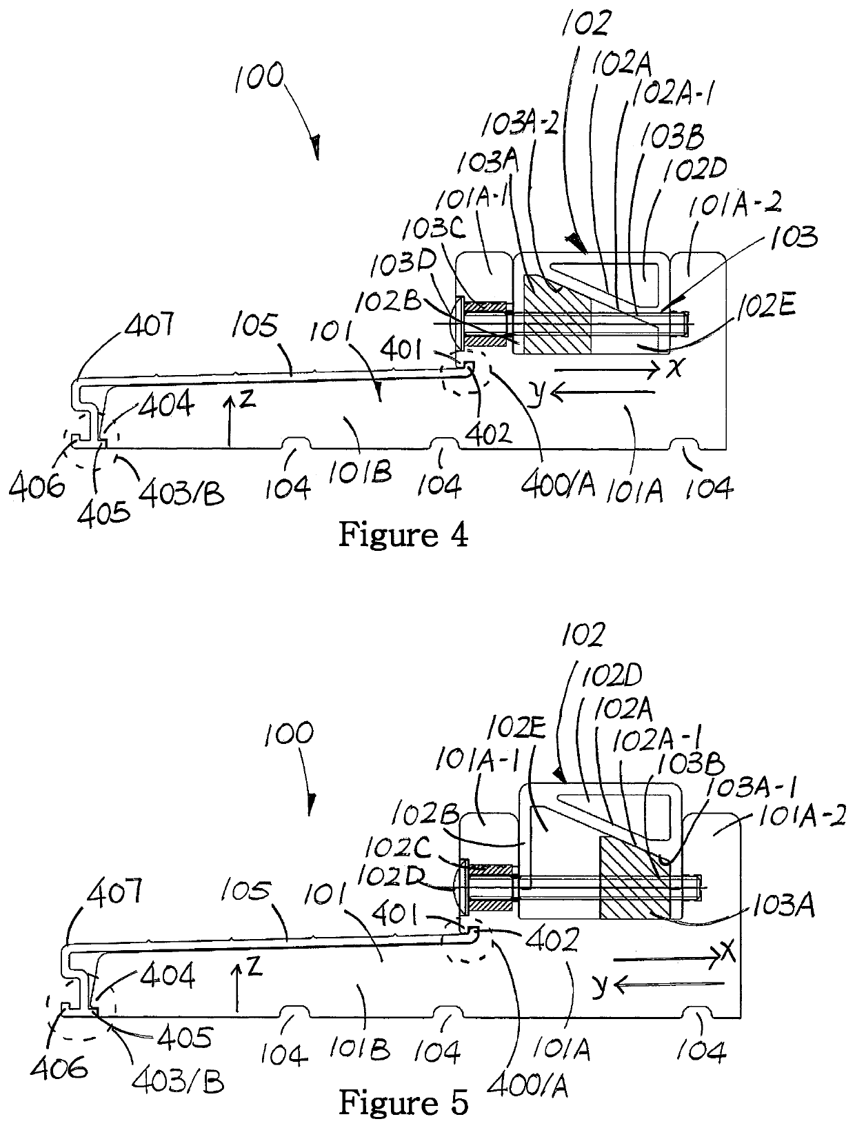
[0018]FIGS. 1 to 7 show a door sill assembly 100 according to the invention.

[0019]As shown in FIGS. 2 and 3, when a door 200 is used with the door sill assembly 100, a gap 300 is left between bottom of the door 200 and top of the door sill assembly 100. The door 200 is a barrier against the external environment. The gap 300 must be sealed off to complete the barrier. To this end, it is common for conventional doors to include a changeable door bottom. In FIGS. 3 and 4, the door 200 is shown to have a replaceable door bottom 201 on its lower end. The door bottom 201 is equipped with fins 202 that function as weather guards. However the weather guards are readily deformable and hence may not be considered as the most effective barrier. Such door bottom 201 may be used with the door sill assembly 100 to enhance the guarding effect. As the fins 202 are deformable, it will be compressed to form a seal between the bottom of the door 200 and the door sill assembly 100. The extent to which ...


PUM

PropertyMeasurementUnit
vertical displacementaaaaaaaaaa
degree of angular movementaaaaaaaaaa
degree of the linear movementaaaaaaaaaa

Abstract

A door sill assembly for a door comprises a sill, having a lower portion and an adjustable upper portion positioned on the lower portion. The adjustable upper portion is vertically displaceable relative to the lower portion by movement of an adjuster that is available for manipulation when said door is closed. The door sill assembly may include a threshold. The threshold has a body. The body includes front and rear engagement parts integrally formed thereon to bring about first and second engagements respectively. The release of the second engagement is dependent on that of the first engagement.

Description

[0001]The present invention relates to a door sill assembly for use with a door, for example particularly, but not exclusively, a door sill assembly with adjustable height.BACKGROUND OF THE INVENTION[0002]A door sill is part of a door frame that extends along the bottom of the door frame. It usually sits directly on the foundation of the floor.[0003]Instead of a solid piece of wood block, recent developments offer door sill in the form of an assembly with moveable parts. This permits adjustment of height of the door sill to offer flexibility. It is also an attempt to mitigate the cost implication on production of door sill with tailored height. Sill parts can be manufactured by mass production and the height adjustment is made on site.[0004]Door sill with height adjustment can be used with doors of any heights. The adjustable door sill closes off any gaps between the door sill and the bottom of the door, which as a result offers good isolation from the external environment. A proble...

Claims


Application Information

Patent Timeline
13 Feb 2020
Publication
US20200048954A1
IPC
E06B1/70
CPC
E06B1/70; E06B1/342; E06B7/2316
Inventors
WANG, KUEI-YUNG