Door guide system with modular threshold track

Active Publication Date: 2017-09-28
ASSA ABLOY ENTRANCE SYST
View PDF2 Cites 2 Cited by
  • Summary
  • Abstract
  • Description
  • Claims
  • Application Information

AI Technical Summary

Benefits of technology

[0007]One aspect of the present invention provides for a guide system that guides the bottom edge of an automatic sliding door along the floor and that can disengage the bottom of the door upon impact without damage to the door or floor guide. It is a further aspect of the invention to provide

Problems solved by technology

As a result, repair and maintenance of these doors is costly.
In commercial settings, for example, DIY (do it yourself) stores, automatic doors and their guide tracks located on the floor at the threshold of the door are subject to significant wear and damage due to high levels of consumer traffic and the movement of machinery such as forklifts, hand trucks, and pallet movers through the door.
In addition, these doors are also exposed to large amounts of debris which can interfere with the sliding operation of the door.
The guide track is also exposed to rainwater, snow, ice, ice melting agents and other debris from outside the building.
A problem with known pin guide assemblies and pin guide track systems is that they are subject to damage when the pin guide assembly and/or the pin guide track area of the door is impacted from misuse of the door.
For example, if the door is subject to impact in a manner that forces the pin guide assembly out of the pin guide track, such as impact at the heel of the door, the pin guide assembly, the pin guide track, or both may be damaged.
Another problem with known pin guide assemblies and pin guide tracks is that debris can fall into the slot of the pin guide track, jamming the track, preventing or inhibit

Method used


Image

  • Door guide system with modular threshold track
  • Door guide system with modular threshold track
  • Door guide system with modular threshold track

Examples


Embodiment Construction

[0032]Embodiments of the invention are described below with reference to the accompanying drawings. It is to be understood, however, that the invention encompasses other embodiments that are readily understood by those of ordinary skill in the field of the invention. Also, the invention is not limited to the depicted embodiments and the details thereof, which are provided for purposes of illustration and not limitation.

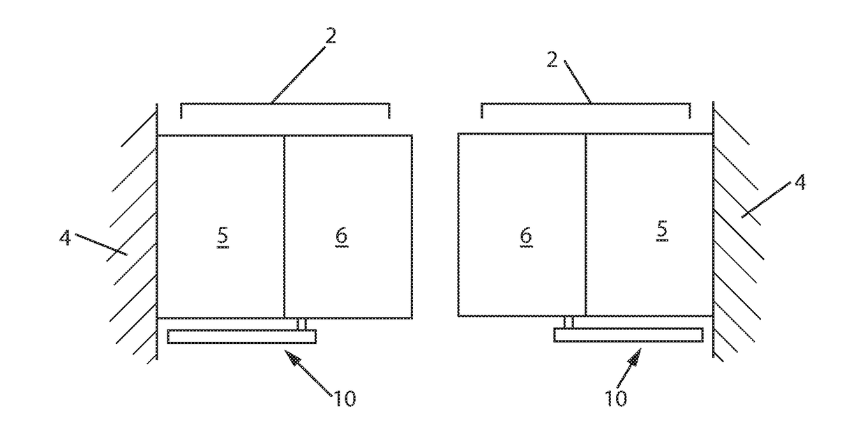
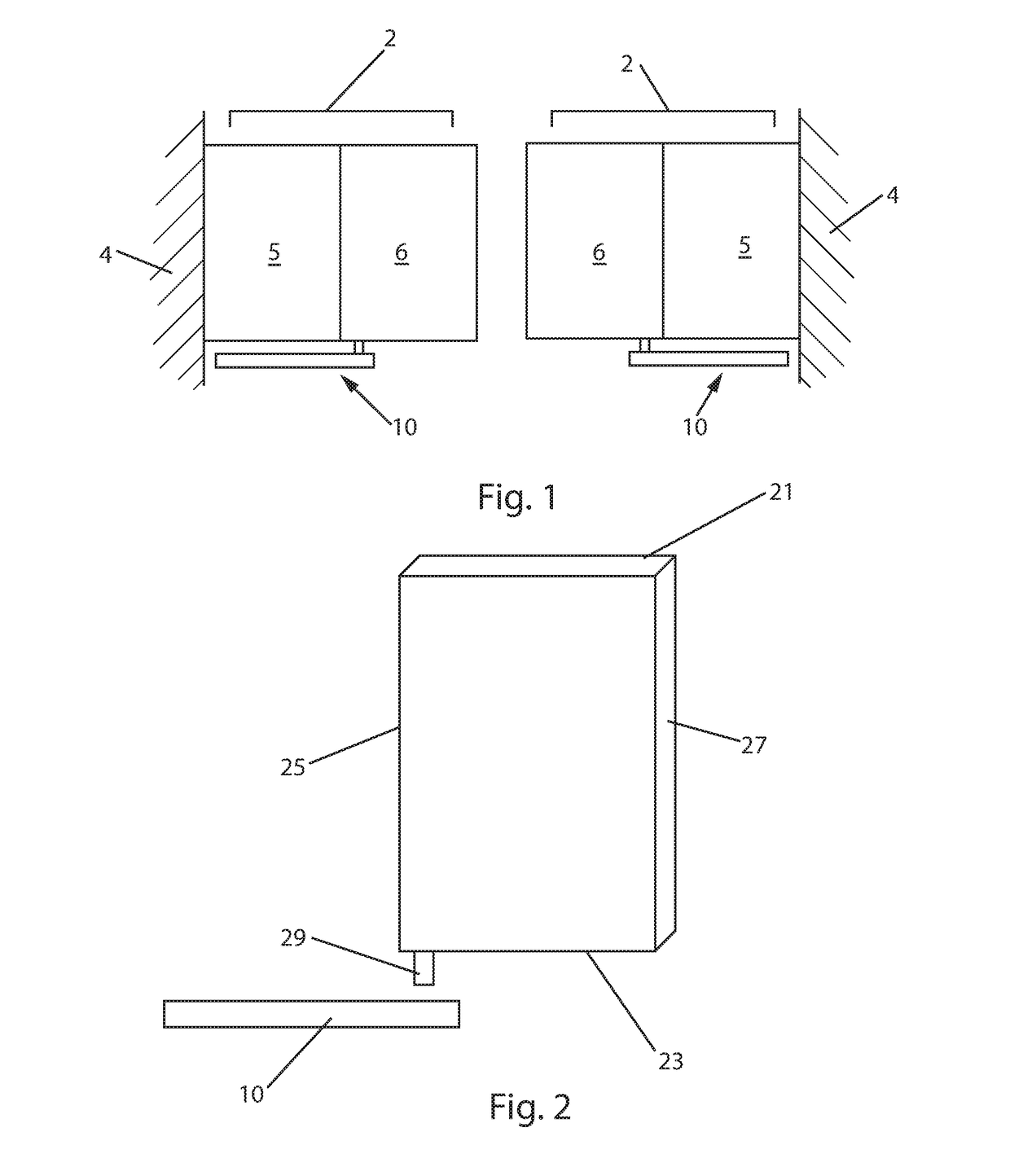
[0033]FIG. 1 shows a sliding door 2 and floor guide assembly 10 in accordance with an embodiment of the present invention. The door may be provided in a wall 4 of a building or other structure such as a commercial or industrial building. In this embodiment, the door 2 is composed of two stationary panels 5 and two sliding door panels 6, sometimes referred to as a bi-parting slider. The sliding panels 6 are supported at the top by a track (not shown) that supports the weight of the panels 6, and allows them to slide to open and close the door 2. The door 2 may also inc...


PUM


Abstract

A sliding door and floor guide assembly including a floor guide and at least one door panel including a pin guide assembly, and a guide shoe. The guide shoe has a curved bottom surface and the rail has a corresponding curved upper surface so that the two surfaces can engage one another. The pin guide assembly includes a spring that exerts a downward force to keep the guide shoe and rail in contact with one another. The guide shoe also includes at least one beveled surface adjacent the region where the guide shoe and rail engage. This beveled surface causes debris on the rail to be moved away from the rail when the door is opened or closed so that the debris does not interfere with the operation of the sliding door.

Description

FIELD OF THE INVENTION[0001]This invention relates to floor guide systems for automatic sliding doors. More particularly, the invention relates to a floor guide and alignment device for a sliding door that enables the door to swing if it is subject to impact and that resists jamming and excessive wear when the floor guide is exposed to debris, such as in industrial and commercial buildings.BACKGROUND OF THE INVENTION[0002]Automatic sliding doors are used in commercial and non-commercial settings in order to allow people and things to enter and exit a given area without having to open and close the door manually. Automatic sliding doors are subject to almost constant use, particularly in commercial and industrial buildings. As a result, repair and maintenance of these doors is costly. In commercial settings, for example, DIY (do it yourself) stores, automatic doors and their guide tracks located on the floor at the threshold of the door are subject to significant wear and damage due ...

Claims


Application Information

Patent Timeline
IPC IPC(8): E05D15/06E05F5/00
CPCE05D15/0682E05Y2900/132E05F5/003E05D15/0656E05D15/0686E05Y2201/474E05Y2201/708E05Y2800/404E05Y2800/412E05Y2800/43
Inventor WOLFE, JEFFREY A.
Owner ASSA ABLOY ENTRANCE SYST
Why Eureka
Try Eureka