Assembly for and method of gripping sheets of material in an interfolder

a technology of interfolding machine and interfolding sheet, which is applied in the direction of folding thin materials, thin material processing, mechanical working/deformation, etc., can solve the problems of known gripper assemblies, reducing shaft/bearing life, and each bushing being subject to wear and potential failure and replacement, so as to prevent contaminants

Inactive Publication Date: 2008-02-12
FABIO PERINI SPA
View PDF21 Cites 11 Cited by
  • Summary
  • Abstract
  • Description
  • Claims
  • Application Information

AI Technical Summary

Benefits of technology

[0006]In accordance with the present invention, a gripper assembly for a folding roll permits the use of a hardened steel shaft material by eliminating the machining required to form a prior art gripper assembly mounted with exposed bushings. The shaft is configured with a spacer arrangement that eliminates the need to machine the shaft. The gripper assembly further includes a series of lubricated bearings that are sealed in housings to preventing contaminants from entering the bearings.
[0008]The bolt of the gripper assembly is threaded, and the shaft includes a threaded opening to receive the threaded bolt. The shaft includes a radially extending counterbore configured to receive at least a portion of the bolt. The counterbore in the shaft is in alignment with the opening in the blade and is sized to receive the bolt. The spacer includes an opening in alignment with the counterbore to receive the bolt. The spacer includes an arcuate-shaped surface that interfaces with the shaft. The shaft is comprised of a hardened-steel material, and is mounted in a series of interior and end mounted housing assemblies that include housings containing one or more lubricated needle bearings. The interior and end mounting housing assemblies further include seals to prevent debris from contaminating the bearings.

Problems solved by technology

However, known gripper assemblies have several drawbacks.
Furthermore, each folding roll includes a number of shafts, each of which is mounted using a number of such bushings, and each bushing constitutes a component that is subject to wear and potential failure and replacement.
The folding roll operates in an environment in which the bushings are subject to introduction of contaminants, which can reduce shaft / bearing life and increase the torque required to rotate the shaft.
Furthermore, the shaft of a gripper assembly of this type requires extensive low tolerance machining to assemble.
Because of this machining requirement, it is not possible to use a hardened steel material for the gripper assembly shaft.

Method used


Image

  • Assembly for and method of gripping sheets of material in an interfolder
  • Assembly for and method of gripping sheets of material in an interfolder
  • Assembly for and method of gripping sheets of material in an interfolder

Examples


Embodiment Construction

1. Interfolding Machine

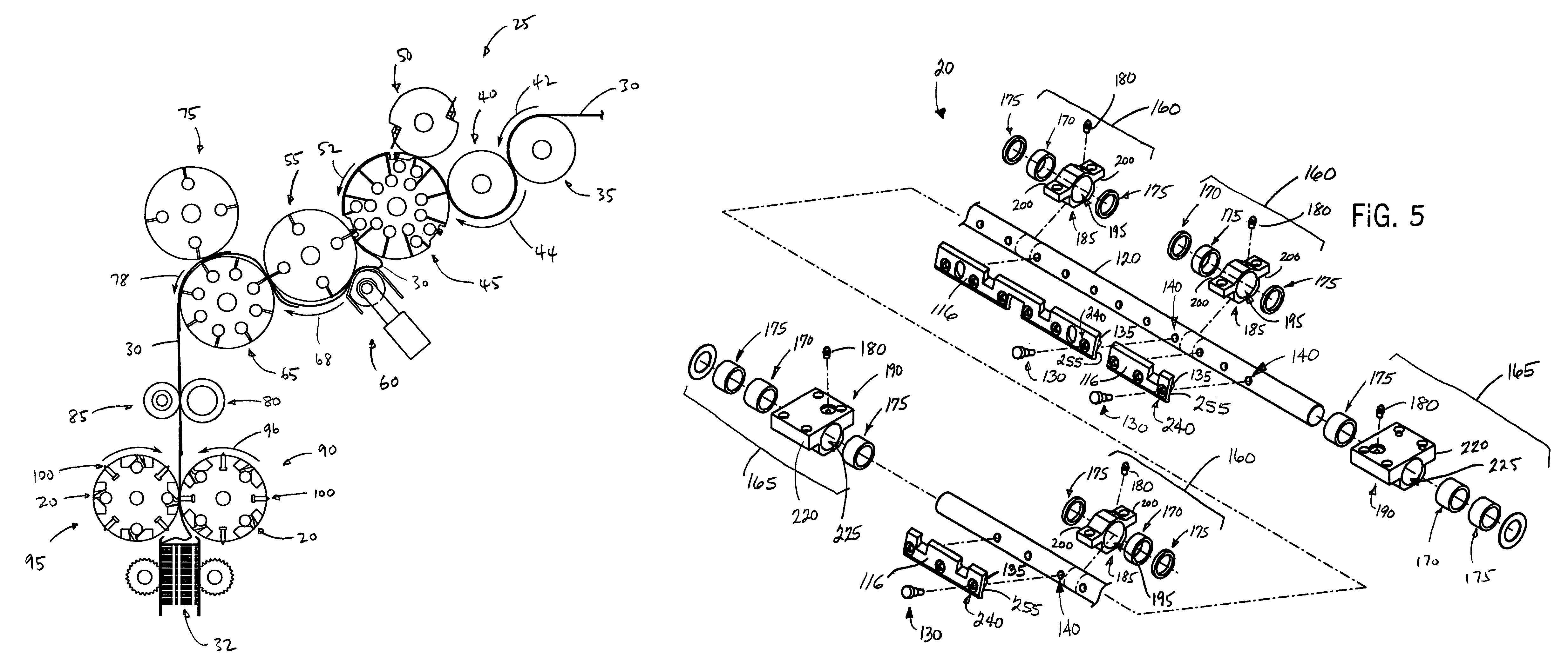
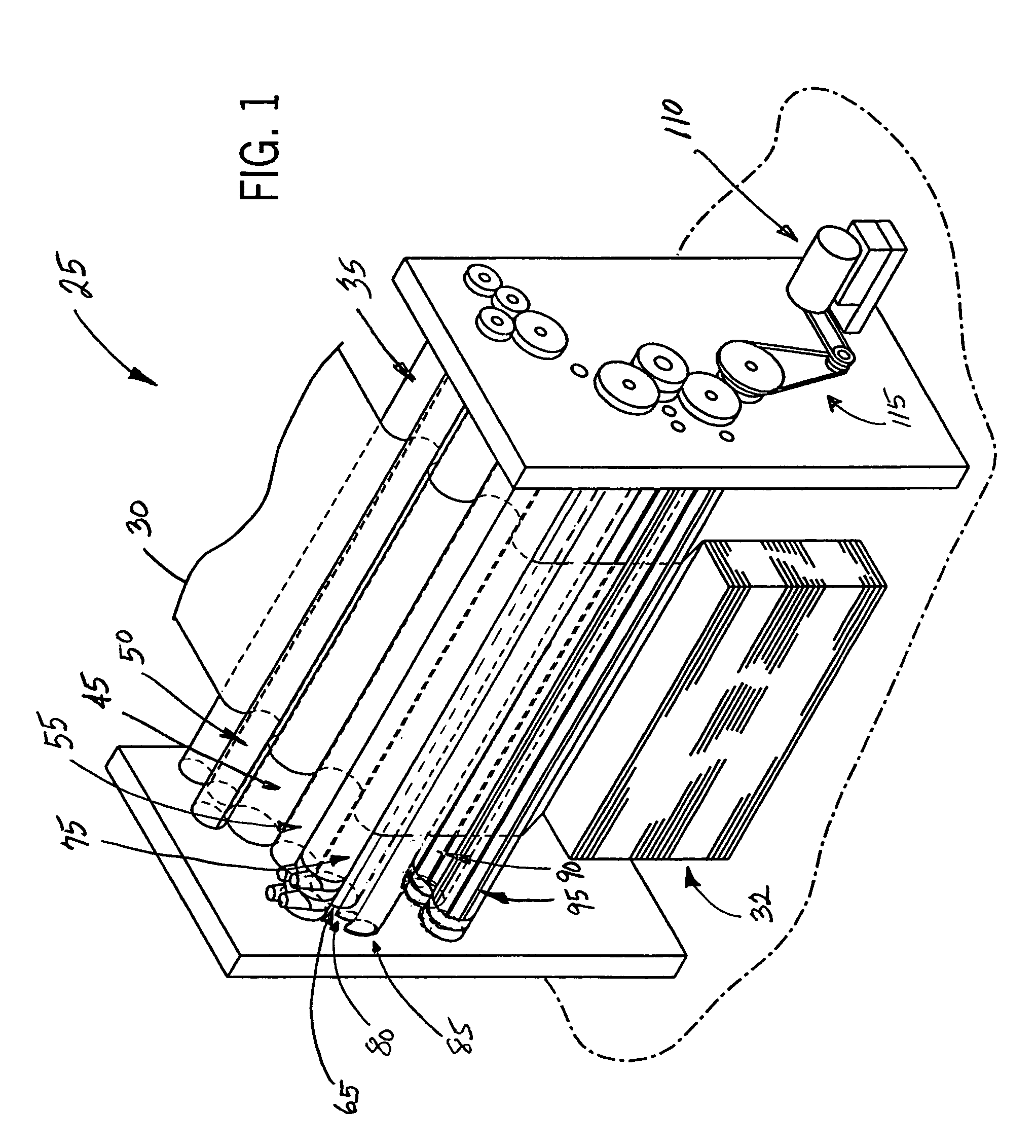
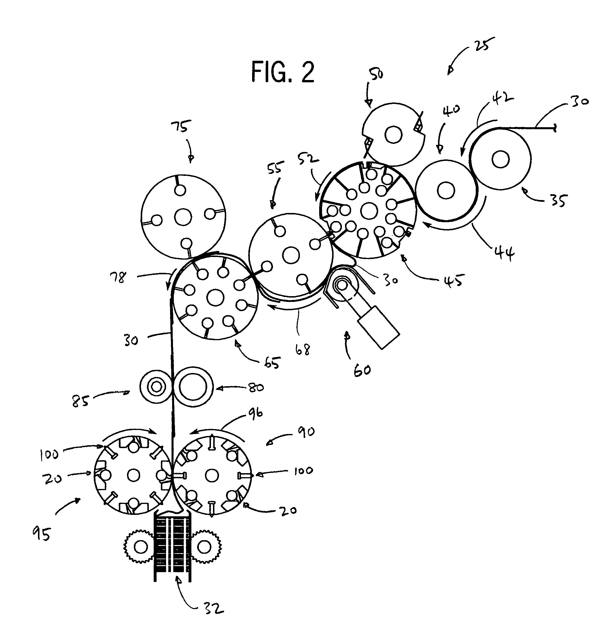
[0019]Referring to FIGS. 1 and 2, an interfolding machine 25 is operable to convert a web of material 30 into a stack of interfolded sheets of material shown at 32. Interfolding machine 25 incorporates folding rolls incorporating the gripper assembly of the present invention, and generally includes a first pull roll 35 and a second pull roll 40 that receive the web of material 30 along a path (illustrated by an arrow 42 in FIG. 2) from a supply roll (not shown) into the interfolding machine 20. The first and second pull rolls 35 and 40 define a nip through which the web of material 30 passes, and function to unwind the web of material 30 and feed the web of material 30 in a path (illustrated by an arrow 44 in FIG. 2) toward a nip defined between second pull roll 40 and a bed roll 45. The web of material 30 is then advanced by bed roll 45 toward a knife roll 50. In a manner as is known, the knife roll 50 cuts the web of material 30 into sheets, each of which ha...


PUM

PropertyMeasurementUnit
areaaaaaaaaaaa
circumferenceaaaaaaaaaa
torqueaaaaaaaaaa

Abstract

A folding machine includes a first folding roll with a series of the gripper assemblies and a series of tucker assemblies uniformly and alternately spaced to interact with a series of gripper and tucker assemblies of an adjacent second folding roll. The series of alternately spaced gripper and tucker assemblies interact to grip, carry, and release material in a manner so as to generate a folded stack of material, such as sheet material. Each of the gripper assemblies generally includes a rotatable blade, a shaft configured to rotate the blade, a spacer disposed between the blade and the shaft, and a bolt coupling the blade and the spacer to the shaft. A housing is configured with seals to retain lubricated bearings to provide rotation of the shaft of the gripper assembly and to prevent contamination of the bearings.

Description

RELATED APPLICATIONS[0001]This application claims the benefit under 35 U.S.C. § 119(e) of U.S. Provisional Application Ser. No. 60 / 507,392, filed Sep. 30, 2003, the entirety of which is hereby incorporated herein by reference.FIELD OF THE INVENTION[0002]This invention generally relates to an interfolding machine for interfolding sheets of material, and more specifically, to an interfolding machine that includes a folding roll having an assembly configured for gripping the sheets of material to create a fold in the sheets.BACKGROUND OF THE INVENTION[0003]Folding of sheets of material (e.g., paper, napkins, paper towels, tissue, etc.) is frequently performed using a pair of folding rolls that have interacting mechanical gripper and tucker assemblies. The gripper and tucker assemblies are uniformly spaced around a circumference of each respective folding roll to interact with one another so as to interfold the sheets of material. The tucker assemblies on one roll interact with the grip...

Claims


Application Information

Patent Timeline
Patent Type & Authority Patents(United States)
IPC IPC(8): B31F1/10B65H45/16B65H45/24
CPCB65H45/165B65H45/24B65H2405/54B65H2701/1924B65H45/163
Inventor HAASL, ANDREW L.WHITE, BARTON J.
Owner FABIO PERINI SPA
Why Eureka
Try Eureka