B-pillar lower end outer threshold angle plate structure

A technology for outer sills and gussets, applied in superstructures, superstructure subassemblies, transportation and packaging, etc., can solve the problems of high intrusion speed and large intrusion of column collisions, so as to reduce strength and increase anti-deformation ability , to avoid the effect of rapid deformation

Active Publication Date: 2020-11-10
ZHEJIANG LEAPMOTOR TECH CO LTD
View PDF7 Cites 2 Cited by
  • Summary
  • Abstract
  • Description
  • Claims
  • Application Information

AI Technical Summary

Problems solved by technology

[0005] The structure described in the above-mentioned patent enables the body of the B-pillar to withstand a sufficient impact force when it is subjected to a side collision, and has sufficient strength to ensure that the threshold will not be turned over during the collision, causing excessive immersion of the B-pillar and causing side deformation; the problem is that, considering Due to the strictness of the pillar collision, the addition of parts at the threshold of the lower end of the B-pillar used in the above invention cannot solve the problem of large amount of pillar collision intrusion and high penetration speed.

Method used


Image

  • B-pillar lower end outer threshold angle plate structure
  • B-pillar lower end outer threshold angle plate structure
  • B-pillar lower end outer threshold angle plate structure

Examples


Embodiment

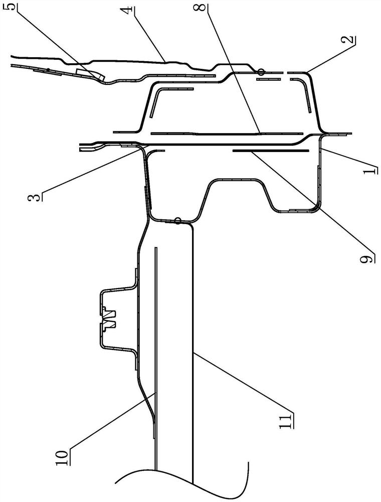
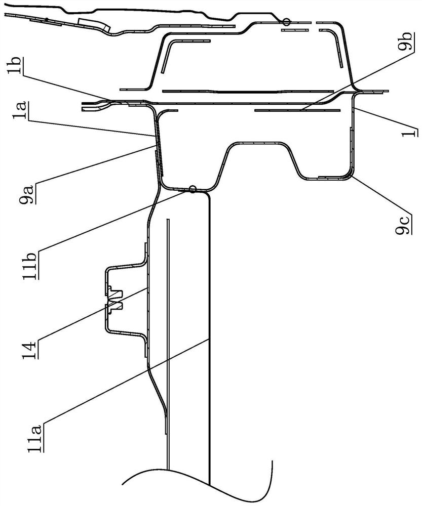
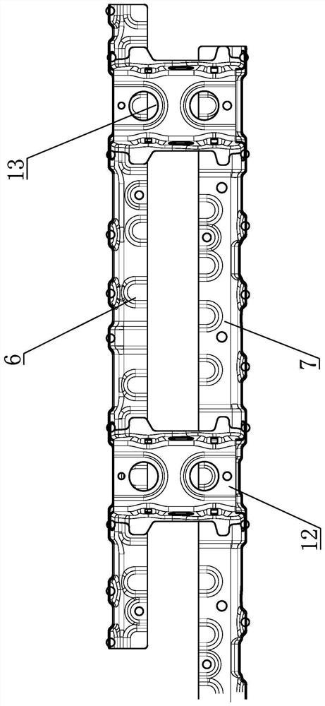
[0028] Such as Figure 1 to Figure 4As shown, a B-pillar lower outer sill gusset structure includes a B-pillar assembly and a sill assembly, the sill assembly includes an inner sill 1 and an outer sill 2 arranged oppositely, and the B-pillar assembly includes a B-pillar inner Panel 3, the side of the outer sill away from the B-pillar inner panel is connected to the side wall outer panel 4, the B-pillar reinforcement plate 5 is provided between the side wall outer panel and the outer sill, and the side of the outer sill close to the B-pillar inner panel is provided with The gusset assembly, the gusset assembly includes a first gusset 6 and a second gusset 7 arranged at intervals, a gusset bracket 8 is provided between the first gusset and the second gusset, and the inner door sill is close to a part of the inner panel of the B-pillar The side is provided with an inner door sill bracket 9, and the side of the inner door sill away from the inner panel of the B-pillar is provided ...


PUM


Abstract

The utility model discloses a B column lower end outer doorsill angle plate structure, and aims to solve the technical problems of large column collision invasion amount and high invasion speed whichcannot be well solved by taking measures of increasing material thickness or adding parts at a B column lower end doorsill in the prior art. The structure comprises a B column assembly and a doorsillassembly; the doorsill assembly comprises an inner doorsill and an outer doorsill which are oppositely arranged, the B column assembly comprises a B column inner plate partially attached to the innerdoorsill, the side, away from the B column inner plate, of the outer doorsill is connected with a side wall outer plate, and a B column reinforcing plate is arranged between the side wall outer plateand the outer doorsill; the angle plate assembly comprises a first angle plate and a second angle plate which are arranged at intervals, an angle plate support is arranged between the first angle plate and the second angle plate, an inner threshold support is arranged on the side, close to the B-pillar inner plate, of the inner threshold, a seat beam body and a middle floor are arranged on the side, away from the B-pillar inner plate, of the inner threshold, and the middle floor comprises a middle floor body parallel to the seat beam body.

Description

technical field [0001] The invention relates to the technical field of automobile bodies, in particular to a structure of an outer sill angle plate at the lower end of a B-pillar. Background technique [0002] With the rapid development of my country's automobile industry, users have higher and higher requirements for automobiles, especially in terms of safety, and their understanding of collision safety and other performances is getting deeper and deeper; with the expansion of domestic automobile overseas markets, more and more More and more car manufacturers are going abroad. At the same time, meeting the more stringent requirements of automobile safety regulations has become the design goal of various car manufacturers, among which E-NCAP is the most typical. [0003] Based on the research by Yang Tingfu et al., "Optimization of Car Body in E-NCAP Pillar Impact Requirements", it can be seen that the performance of automobile pillar impact is one of the important evaluation...

Claims


Application Information

Patent Timeline
Patent Type & Authority Applications(China)
IPC IPC(8): B62D25/04B62D25/20
CPCB62D25/04B62D25/2036
Inventor 刘建胜郭大洲
Owner ZHEJIANG LEAPMOTOR TECH CO LTD
Why Eureka
Try Eureka