Flap valve structure of pressure-maintaining coring device

A technology of flap valve and coring device, which is applied in the direction of extracting undisturbed core devices, wellbore/well valve devices, wellbore/well components, etc. Failure and other problems, to achieve the effect of improving the pressure holding capacity, reliable sealing performance, and preventing valve leakage

Pending Publication Date: 2020-02-28
SICHUAN UNIV
View PDF13 Cites 30 Cited by
  • Summary
  • Abstract
  • Description
  • Claims
  • Application Information

AI Technical Summary

Problems solved by technology

But when the valve is closed, the disc and the valve seat have no supporting surface except the sealing cone surface, and the contact pressure is only concentrated on the sealing cone surface, so the pressure bearing capacity is weak. Usually, the sealing will occur when the pressure is greater than 30Mpa. When the conical surface is deformed by force and the seal fails
[0004] In addition, the traditional core taker flap valve is triggered by shrapnel and relies on the gravity of the valve disc itself to realize the cooperative action, so it can only drill in near-vertical conditions.

Method used


Image

  • Flap valve structure of pressure-maintaining coring device
  • Flap valve structure of pressure-maintaining coring device
  • Flap valve structure of pressure-maintaining coring device

Examples


Embodiment 1

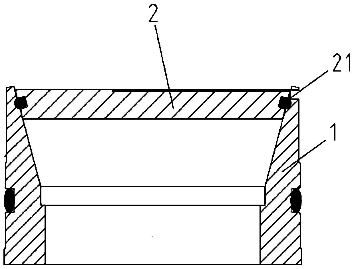
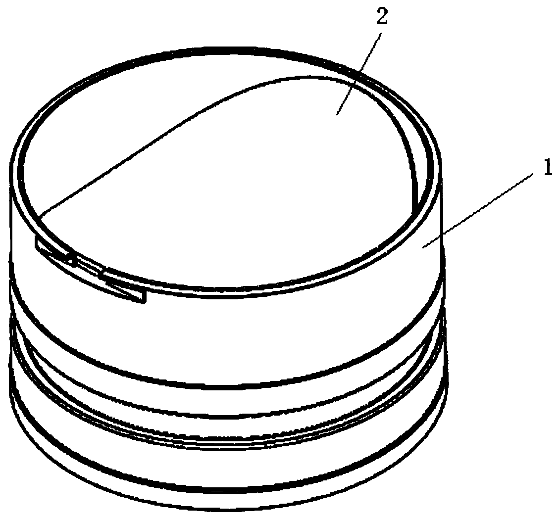
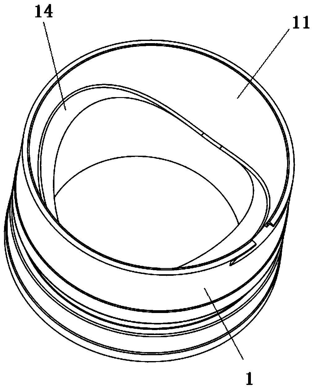
[0038] Such as figure 2 , 3 As shown in , 4, the pressure-maintaining coring device flap valve structure disclosed in this embodiment includes a valve seat 1 and a valve disc 2, one end of the valve disc 2 is movably connected with the upper end of the valve seat 1, and the top of the valve seat 1 is connected to the valve disc 2. Matching valve port sealing surface 11, the valve port sealing surface 11 is a conical surface, the valve disc 2 has a valve disc sealing surface adapted to the valve port sealing surface 11, and the taper of the valve disc sealing surface and the valve port sealing surface 11 is the same .

[0039] There is a supporting surface for supporting the valve disc 2 on the sealing surface 11 of the valve port; when the valve disc 2 is closed, the bottom of the valve disc 2 is against the supporting surface of the valve seat 1 . The coefficient of friction of the bearing surface in this embodiment is 0.12-0.3.

[0040] When the valve clack 2 is closed, ...

Embodiment 2

[0044] The difference between this embodiment and the first embodiment is that: Figure 5-8 As shown, in this embodiment, a groove 15 conformally matched with the valve flap 2 is provided on the valve port sealing surface 11 to form a supporting surface, and the bottom of the valve flap 2 has a convex portion 22 adapted to the groove 15. When the valve flap 2 is closed , the protrusion 22 is embedded in the groove 15 . The cone angle of the sealing surface 11 of the valve port is 40°-50°.

Embodiment 3

[0046] The difference between this embodiment and Embodiment 1 and Embodiment 2 is that: in this embodiment, a magnet is provided on the valve seat 1 , and a magnetic material is provided on the valve flap 2 . The shape, position and quantity of the magnets are set as required. This embodiment only mentions two of them, but is not limited to these two configurations.

[0047] The first type, such as Figure 9 As shown, an annular magnet 6 is installed on the valve seat 1, and the position of the annular magnet 6 is set as required. The annular magnet 6 can be arranged below the sealing groove 16 of the valve seat, and can also be arranged above the sealing groove 16 of the valve seat.

[0048] The second type, such as Figure 10 As shown, the sheet magnets 7 are installed on the valve seat 1, and the number and positions of the sheet magnets 7 are set as required. The magnet can choose NdFeB magnet.

[0049] In this embodiment, the valve flap 2 can be magnetically attract...


PUM


Abstract

The invention relates to a flap valve structure of a pressure-maintaining coring device. The flap valve structure comprises a valve seat and a valve flap, one end of the valve flap is movably connected with the upper end of the valve seat, the top of the valve seat is provided with a valve port sealing surface matched with the valve flap, the valve port sealing surface is a conical surface, the valve flap is provided with a valve flap sealing surface matched with the valve port sealing surface, and the taper of the valve flap sealing surface is the same as the taper of the valve port sealing surface; the valve port sealing surface is provided with a bearing surface for supporting the valve flap; and when the valve flap is closed, the bottom of the valve flap abuts against the bearing surface of the valve seat. According to the flap valve structure of the pressure-maintaining coring device, when the valve flap is closed, displacement constraint is applied to the bottom surface and the side surface of the valve flap, the anti-deformation capability of the sealing surface can be effectively improved, the valve can bear higher pressure, and the pressure maintaining capability of the valve is improved; and the valve seat has magnetism, and the valve flap can be attracted to be closed.

Description

technical field [0001] The invention relates to the technical field of sealing devices for core removers, in particular to the structure of a flap valve for a pressure maintaining core remover. Background technique [0002] At present, in the field of pressure-holding coring, the upper end of the pressure-holding cylinder is generally sealed by a piston, and the lower end of the pressure-holding cylinder is usually sealed by a ball valve or a flap valve. The structure of the ball valve is relatively complex and occupies a large space, which limits the diameter of the drilled core. The processing technology of the ball valve is high, and when the pressure is high, the liquid in the pressure-holding cylinder will leak from the gap between the ball valve and the core cylinder. Unable to maintain high pressure. [0003] Such as figure 1 As shown, the existing flap valve includes a valve seat (serial number 1) and a valve flap (serial number 2), and its structure is simple. Bu...

Claims


Application Information

Patent Timeline
Patent Type & Authority Applications(China)
IPC IPC(8): E21B34/06E21B25/00
CPCE21B34/06E21B25/00
Inventor 吴年汉陈领高明忠李聪李佳南何志强杨明庆余波胡云起黄伟
Owner SICHUAN UNIV
Why Eureka
Try Eureka