Exercise Machine with Levitated Platform

a technology of exercise platform and exercise machine, which is applied in the direction of resistance force resistor, gymnastic exercise, sport apparatus, etc., can solve the problems of adding an unknown resistance level, affecting the use and enjoyment of the exercise machine by the exerciser, and a level of friction that remains due, so as to eliminate contact friction and additional resistance

Active Publication Date: 2020-02-20
LAGREE TECH INC
View PDF0 Cites 20 Cited by
  • Summary
  • Abstract
  • Description
  • Claims
  • Application Information

AI Technical Summary

Benefits of technology

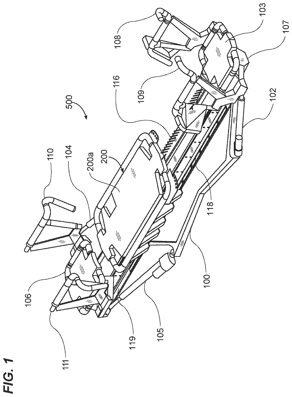
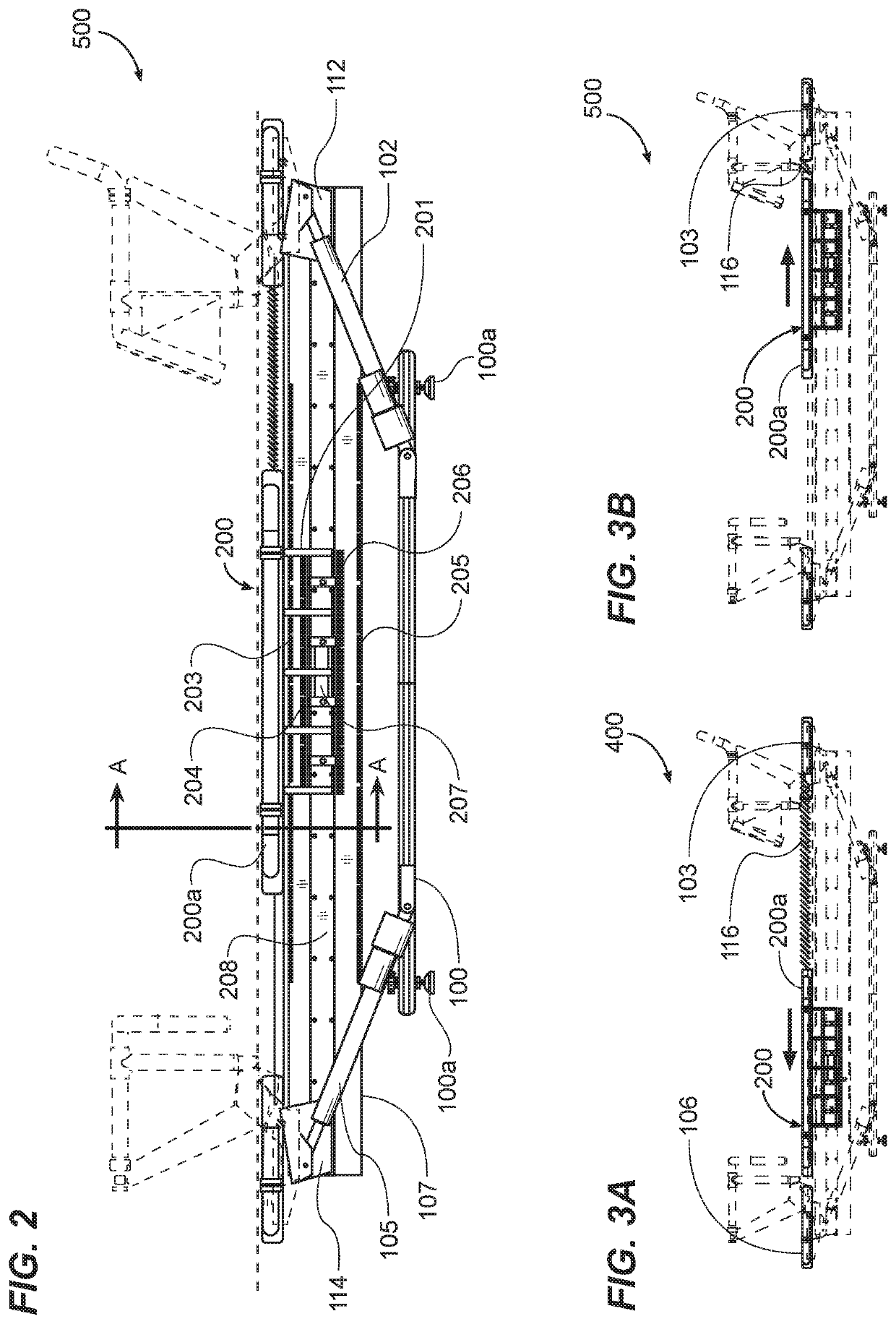
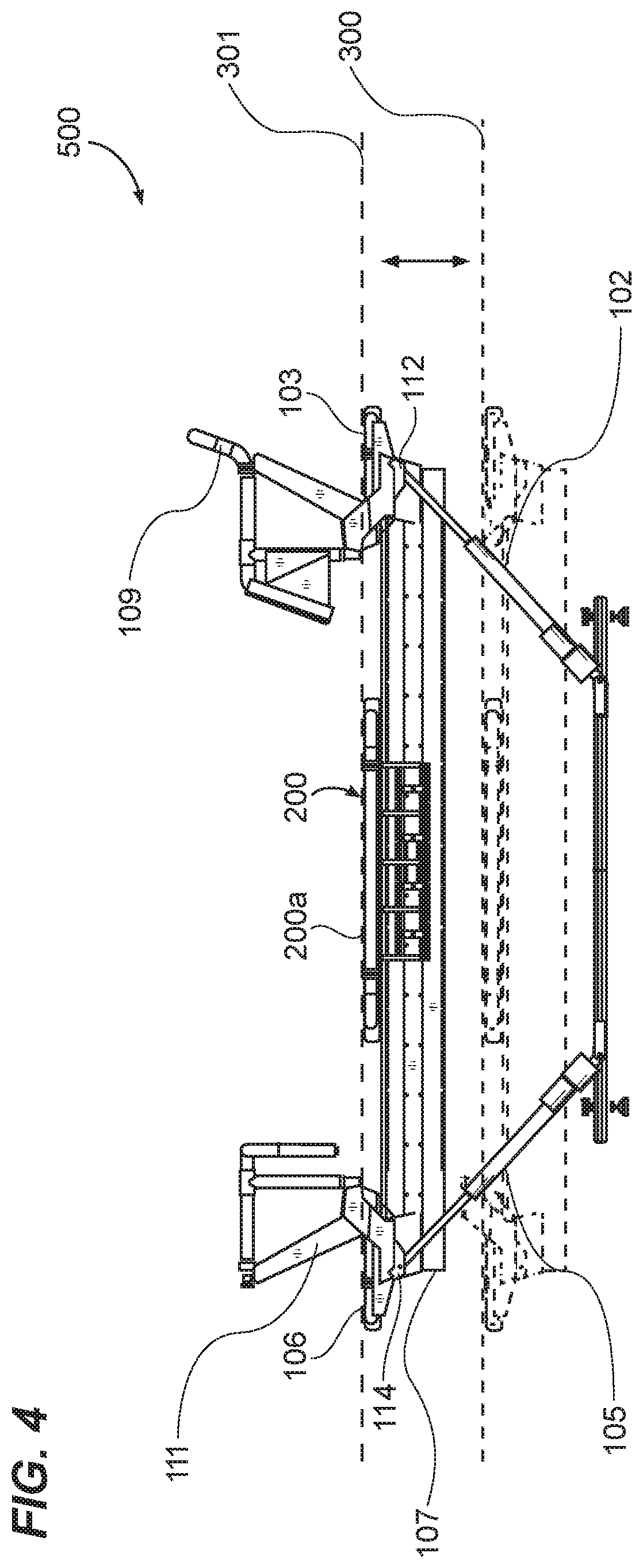
[0014]The movable carriage and platform are levitated relative to the stationary rail structure by magnetic forces generated by an arrangement of magnetic elements on opposing adjacent surfaces of the carriage and the rail structure. Preferably, the magnetic elements are arranged so that the movable carriage and platform are levitated and have substantially no contact with the stationary rail structure over substantially the entire length the movable platform is intended to travel between the stationary platforms, thus substantially eliminating contact friction and additional resistance when the platform is moved relative to the rail structure.
[00...

Problems solved by technology

In machines and apparatuses of the type described above, regardless of the use of wheels or other means intended to reduce friction between the movable platform and stationary rail components, there always remains a level of friction due to contact between the movable and stationary components.
This undesired friction may be experienced by an exerciser and may interfere with the exerciser's use and enjoyment of the machine.
In addition, the undesired friction adds an unknown level of resistance to the known level of resistance set on the machine by an exerciser or trainer and against which the exerciser intends to work during ...

Method used


Image

  • Exercise Machine with Levitated Platform
  • Exercise Machine with Levitated Platform
  • Exercise Machine with Levitated Platform

Examples


Embodiment Construction

[0041]Various aspects of specific embodiments are disclosed in the following description and related drawings. Alternate embodiments may be devised without departing from the spirit or the scope of the present disclosure. Additionally, well-known elements of exemplary embodiments will not be described in detail or will be omitted so as not to obscure relevant details. Further, to facilitate an understanding of the description, a discussion of several terms used herein follows.

[0042]The word “exemplary” is used herein to mean “serving as an example, instance, or illustration.” Any embodiment described herein as “exemplary” is not necessarily to be construed as preferred or advantageous over other embodiments. Likewise, the term “embodiments” is not exhaustive and does not require that all embodiments include the discussed feature, advantage or mode of operation.

[0043]The word “magnet,” the phrase “magnetic element,” and variations thereof as used herein include permanent magnets such...


PUM


Abstract

An improved exercise machine has a stationary longitudinal monorail structure that extends between front and back end stationary exercise platforms, and an exercise platform mounted on a levitated carriage that is reciprocally movable along the monorail between the stationary platforms. Magnetic elements arranged on various opposing surfaces of the carriage and monorail generate magnetic forces that levitate and stabilize the carriage as it moves relative to the monorail thus substantially eliminating contact friction. Springs selectively attachable to the movable platform provide a resistance force for exercising. Pseudo-levitation and eddy brake elements on the carriage and monorail structure further stabilize the carriage and platform.

Description

CROSS REFERENCE TO RELATED APPLICATIONS[0001]I hereby claim benefit under Title 35, United States Code, Section 119(e) of U.S. provisional patent application Ser. No. 62 / 719,837 filed Aug. 20, 2018. The 62 / 719,837 application is currently pending. The 62 / 719,837 application is hereby incorporated by reference into this application.STATEMENT REGARDING FEDERALLY SPONSORED RESEARCH OR DEVELOPMENT[0002]Not applicable to this application.BACKGROUNDField[0003]Example embodiments in general relate to the field of sports and fitness training and exercising equipment. More specifically, example embodiments relate to a machine equipped for resistance training or exercise with a magnetically levitated movable exercise platform.Related Art[0004]Any discussion of the related art throughout the specification should in no way be considered as an admission that such related art is widely known or forms part of common general knowledge in the field.[0005]There are a variety of different designs for ...

Claims


Application Information

Patent Timeline
IPC IPC(8): A63B21/005A63B22/00A63B21/00A63B21/02
CPCA63B21/023A63B21/4033A63B21/0051A63B22/0087A63B21/4045A63B21/0552A63B2071/0063A63B21/0428A63B2209/08A63B24/0087A63B21/00065A63B2071/0683A63B22/0089A63B22/203A63B21/0052A63B21/062A63B21/068A63B21/005
Inventor LAGREE, SEBASTIEN ANTHONY LOUISPAFUNDI, MIRKOGIBBS, ANDY H.
Owner LAGREE TECH INC
Why Eureka
Try Eureka