
Large Bore Pierce Pin for an Inflator

Active Publication Date: 2020-02-20
HALKEY ROBERTS CORP
View PDF0 Cites 1 Cited by
  • Summary
  • Abstract
  • Description
  • Claims
  • Application Information

AI Technical Summary

Benefits of technology

The invention is a large bore pierce pin that is used to quickly fill an inflatable device, like an airline emergency raft, with gas. The pierce pin punctures the seal of a gas cartridge connected to the inflator, allowing the gas to flow into the inflatable device at a desired speed. The pierce pin has an inwardly extending tab that prevents any debris from getting back into the inflator and blocking the gas flow. This design ensures the safe and efficient inflation of the inflatable device.

Problems solved by technology

Unfortunately, however, a large-bore pierce pin may core the frangible seal of the gas cartridge producing a floating chip or “slug” that might be blown back into the inflator by the high pressure gas now flowing from the gas cartridge into the inflator.
The floating slug may then clog the inflator's inflation manifold, significantly reducing the rate of filling of the raft inflator.

Method used


Image

  • Large Bore Pierce Pin for an Inflator
  • Large Bore Pierce Pin for an Inflator
  • Large Bore Pierce Pin for an Inflator

Examples


Embodiment Construction

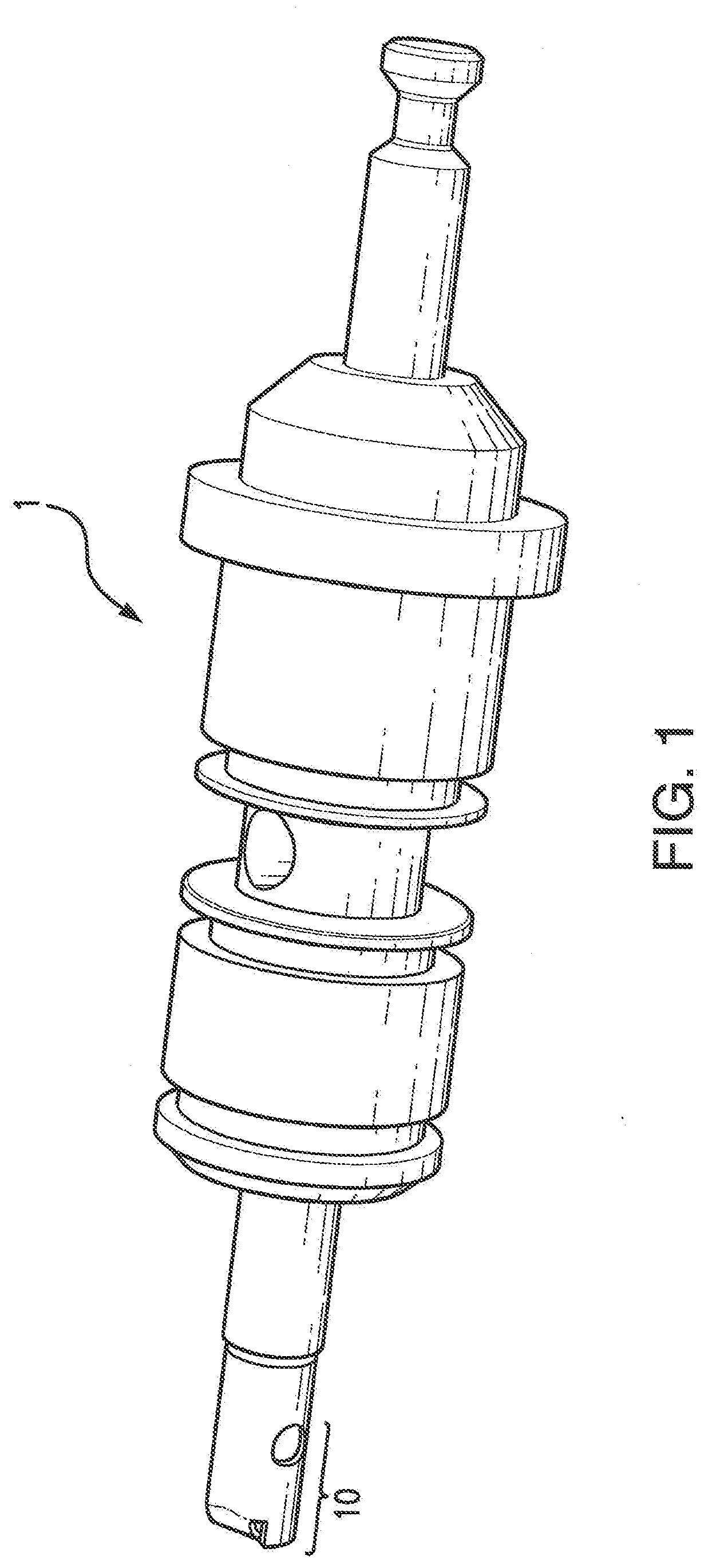
[0020]FIG. 1 is a perspective view of the pierce pin 10 of the invention incorporated into a typical pierce pin assembly 1. The pierce pin 10 of the invention may be incorporated into various types of pierce pin assemblies 1 and therefore the pierce pen assembly 1 is shown in phantom.

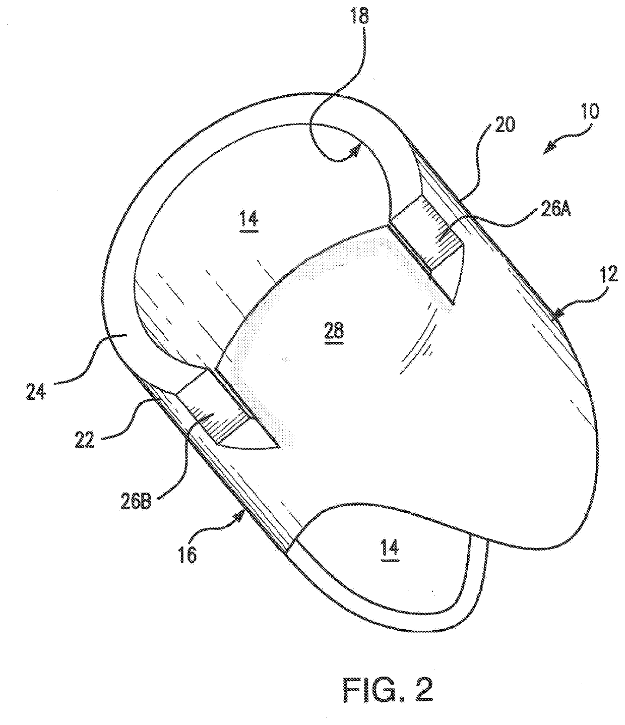
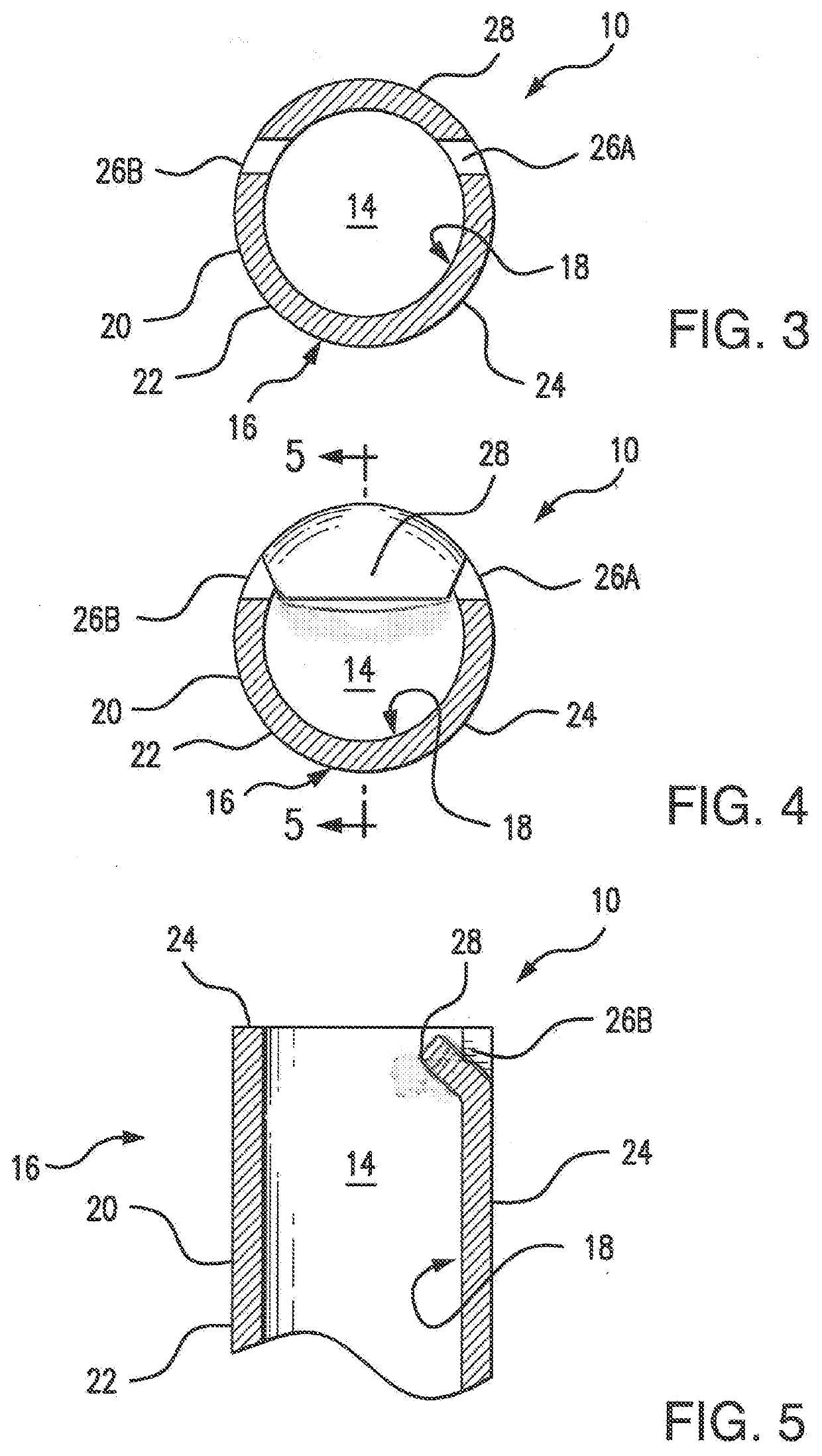
[0021]The pierce pin 10 of the present invention comprises a generally circular cylindrical shaft 12 having a circular cylindrical axial bore 14 forming a tubular member 16. The diameter of the axial bore 14 is designed to achieve the desired rate of flow of the gas escaping the gas cartridge of the inflator. The lumen 18 and the outside surface 20 of the tubular member 16 are generally concentric such that the wall thickness extending from the lumen 18 of the axial bore 14 to the outside surface 20 of the tubular member 16 is generally uniform. Correspondingly, the tip 22 of the pierce pin comprises a generally circular cylindrical rim 24 of uniform thickness.

[0022]A pair of aligned slots 26A and 26B a...


PUM


Abstract

A pierce pin for an inflator for piercing the frangible seal of a gas cartridge including in combination a shaft having a axial bore forming a tubular member having a tip with a rim and a pair of slots formed across the rim into the tip into the tubular member to an appreciable depth to form a tab, the tab being bent inwardly into the axial bore after formation of the slots.

Description

CROSS-REFERENCE TO RELATED INVENTIONS[0001]This application claims the benefit of provisional application No. 62 / 718,915, filed Aug. 14, 2018.BACKGROUND OF THE INVENTIONField of the Invention[0002]This invention relates to inflators. More particularly, this invention relates to inflation valves for compressed gas cylinders used for inflating inflatable articles such as life rafts.Description of the Background Art[0003]Presently there exist many types of inflation valves designed to be used in conjunction with compressed gas cylinders or the like. In their simplest forms, inflation valves include a knob or handle which is turned to open a cylinder of compressed gas to inflate the inflatable article. However, even more prevalent are inflation valves for sealed gas cylinders having a sealed, frangible seal to which the inflator is threadably mounted. Inflation valves of this type are operable by means of a jerk handle and lanyard cord that allow the inflatable article to be quickly inf...

Claims


Application Information

Patent Timeline
IPC IPC(8): B63C9/00B63C9/04
CPCB63C2009/042B63C9/00B63C9/04B63C2009/0023F16K51/00B63C9/19
Inventor FAWCETT, LYMAN
Owner HALKEY ROBERTS CORP
Learn More