
Device For Super Cryogenic Forming Of Metal Thin-Walled Curved Surface Part

Active Publication Date: 2022-03-17
DALIAN UNIV OF TECH
View PDF0 Cites 0 Cited by
  • Summary
  • Abstract
  • Description
  • Claims
  • Application Information

AI Technical Summary

Benefits of technology

This patent describes a method for creating a large volume of super cryogenic medium with a set pressure range of 0.8-30 MPa. The method involves rapidly filling a cavity of a female die with the super cryogenic medium from a cryogenic container and then increasing the pressure of the medium using a cryogenic pump. The technical effect of this method is a faster and more efficient way to create a large volume of super cryogenic medium with a set pressure range.

Problems solved by technology

The integration of a thin-walled curved surface part results in more complex shape and a larger size thereof.
For the sake of light weight, it is necessary to use a high-strength lightweight alloy material, which renders the forming of such a thin-walled curved surface part more difficult.
Taking a fuel tank dome for example, duel to an ultra-thin wall (with a thickness-to-diameter ratio of less than ) and poor room-temperature ductility of the used high-strength aluminum alloy, the problems of wrinkling and cracking of such a thin-walled curved surface part during its integrated forming cannot be solved in the prior art.
Current research on this technique is still at a preliminary stage on an international scale and there is no mature experience that can be used for reference.
During the research on the principle of the super cryogenic forming technique, to achieve uniform cooling, the die is completely immersed in a super cryogenic medium, which results in a series of problems including high consumption of the super cryogenic medium, difficult of batch production, impossible forming of large-size components, etc.
However, the blank cannot be cooled to a low temperature in this way.

Method used


Image

  • Device For Super Cryogenic Forming Of Metal Thin-Walled Curved Surface Part
  • Device For Super Cryogenic Forming Of Metal Thin-Walled Curved Surface Part

Examples


Embodiment Construction

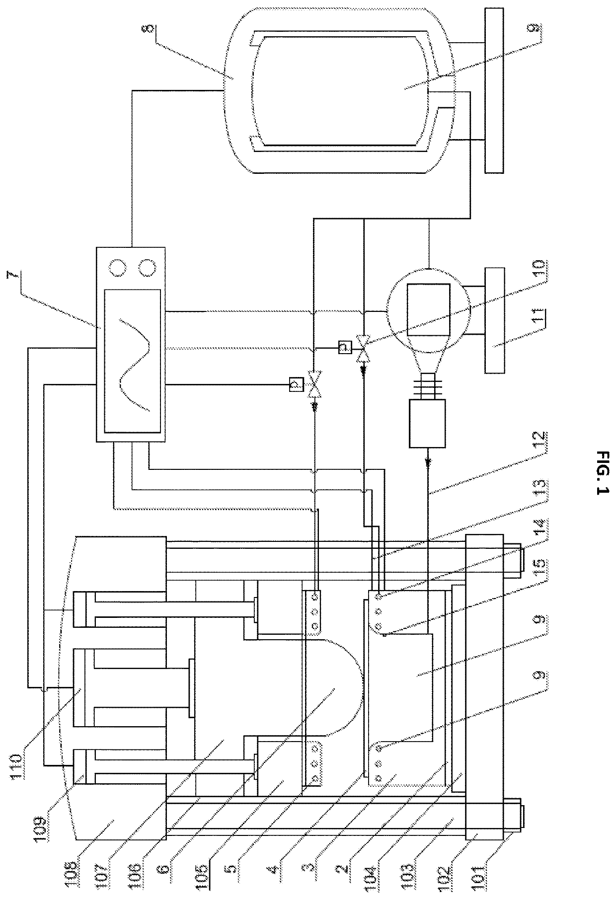
[0024]The technical solutions in the embodiments of the present disclosure will be described below clearly and completely with reference to the accompanying drawings used therein. Apparently, the described embodiments are merely a part rather than all of the embodiments of the present disclosure. All other embodiments derived from the embodiments in the present disclosure by a person of ordinary skill in the art without creative efforts shall fall within the protection scope of the present disclosure.

[0025]An objective of the present disclosure is to provide a device for super cryogenic forming of a metal thin-walled curved surface part to address the problems in the prior art, such that the super cryogenic forming of a metal thin-walled curved surface part can be realized with a super cryogenic medium to directly cool both forming die and blank.

[0026]To make the above-mentioned objectives, features, and advantages of the present disclosure clearer and more comprehensible, the prese...


PUM

PropertyMeasurementUnit
Temperatureaaaaaaaaaa

Abstract

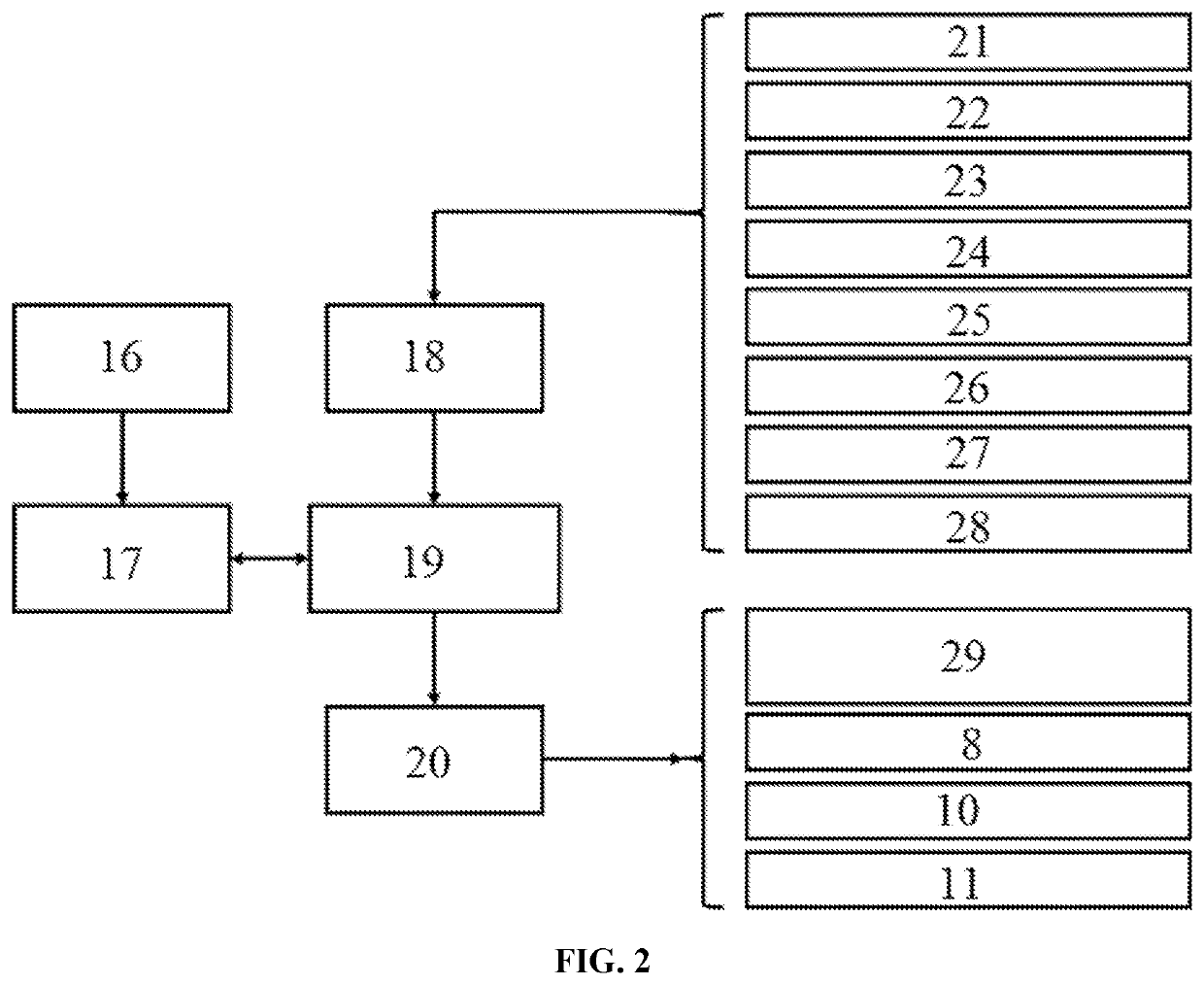
The present disclosure provides a device for super cryogenic forming of a metal thin-walled curved surface part, including a super cryogenic medium conveying and pressurizing unit, a press, a die unit and a control system. A blank holder cylinder, a blank holder slide, a deep drawing cylinder and a deep drawing slide are disposed on the press. The die unit includes a male die, a blank holder and a female die. The super cryogenic medium conveying and pressurizing unit includes an autoboosting cryogenic container. A cryogenic channel in the blank holder, a cryogenic channel in the female die and a cavity of the female die are communicated with an outlet of the autoboosting cryogenic container by cryogenic pipes, respectively. A cryogenic pump is disposed on the cryogenic pipe between the cavity of the female die and the autoboosting cryogenic container.

Description

CROSS REFERENCE TO RELATED APPLICATION[0001]This patent application claims the benefit and priority of Chinese Patent Application No. 202010964727.7 filed on Sep. 15, 2020, the disclosure of which is incorporated by reference herein in its entirety as part of the present application.TECHNICAL FIELD[0002]The present disclosure relates to the technical field of sheet metal forming, and in particular, to a device for super cryogenic forming of a metal thin-walled curved surface part.BACKGROUND ART[0003]Thin-walled curved surface parts are used as key components in vehicles such as rockets, aircrafts, high-speed trains and automobiles. The geometry, dimensional accuracy and overall performance of such a part (e.g., a fuel tank dome for a launch vehicle, an aircraft envelope, an automobile panel) have direct influence on the aerodynamic performance, carrying capacity, payload and service life of the vehicle. To meet the increasingly higher requirements of the new generation of launch veh...

Claims


Application Information

Patent Timeline
IPC IPC(8): B21D37/16B21D22/20
CPCB21D37/16B21D22/20B21D22/205B21D22/22B21D37/10B30B15/26
Inventor YUAN, SHIJIANFAN, XIAOBO
Owner DALIAN UNIV OF TECH
Learn More