Sensor and method for manufacturing a sensor

Pending Publication Date: 2022-02-10
ROBERT BOSCH GMBH
View PDF0 Cites 0 Cited by
  • Summary
  • Abstract
  • Description
  • Claims
  • Application Information

AI Technical Summary

Benefits of technology

The patent describes a way to fill a sensor with a fluid in a simple and cost-effective way. The method has advantages over traditional methods because it allows for flexible electrical signal conduction without compromising the sensor's function. It also reduces the space requirement during manufacturing. Additionally, the method includes a seal on the outer side of the housing, which makes it easier to integrate the sensor into an end product and simplifies the manufacturing process.

Problems solved by technology

However, the fact that the filling under a vacuum is complex and cost-intensive is problematic, as is the increased space requirement and the limited flexibility with respect to the electrical signal conduction through the filling openings spatially separated from the housing / membrane joint.
“Narrow” and “pointy,” in particular, mean that the “self-healing property” of the material of the membrane is not impaired by the design of the object, since the “self-healing property” is usually lost in the case of excessive damage.

Method used


Image

  • Sensor and method for manufacturing a sensor
  • Sensor and method for manufacturing a sensor
  • Sensor and method for manufacturing a sensor

Examples


Embodiment Construction

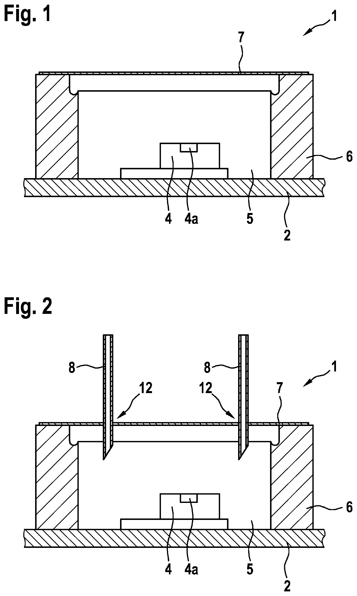
[0044]FIG. 1 shows a sensor according to one specific embodiment of the present invention in the cross-section prior to filling;

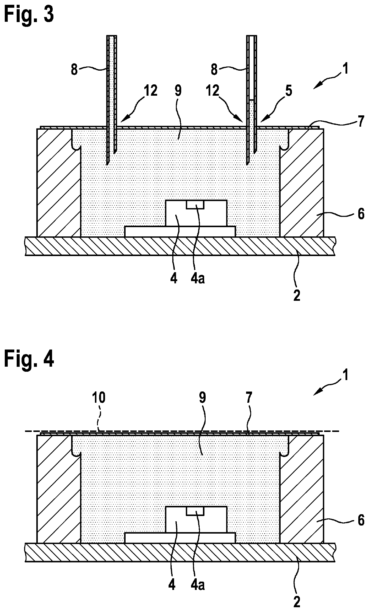
[0045]FIG. 2 shows the sensor according to FIG. 1 including cannulas pushed through the membrane; FIG. 3 shows the sensor according to FIG. 2 including cannulas pushed through the membrane after complete filling; and FIG. 4 shows the sensor according to FIG. 3 in the final state.

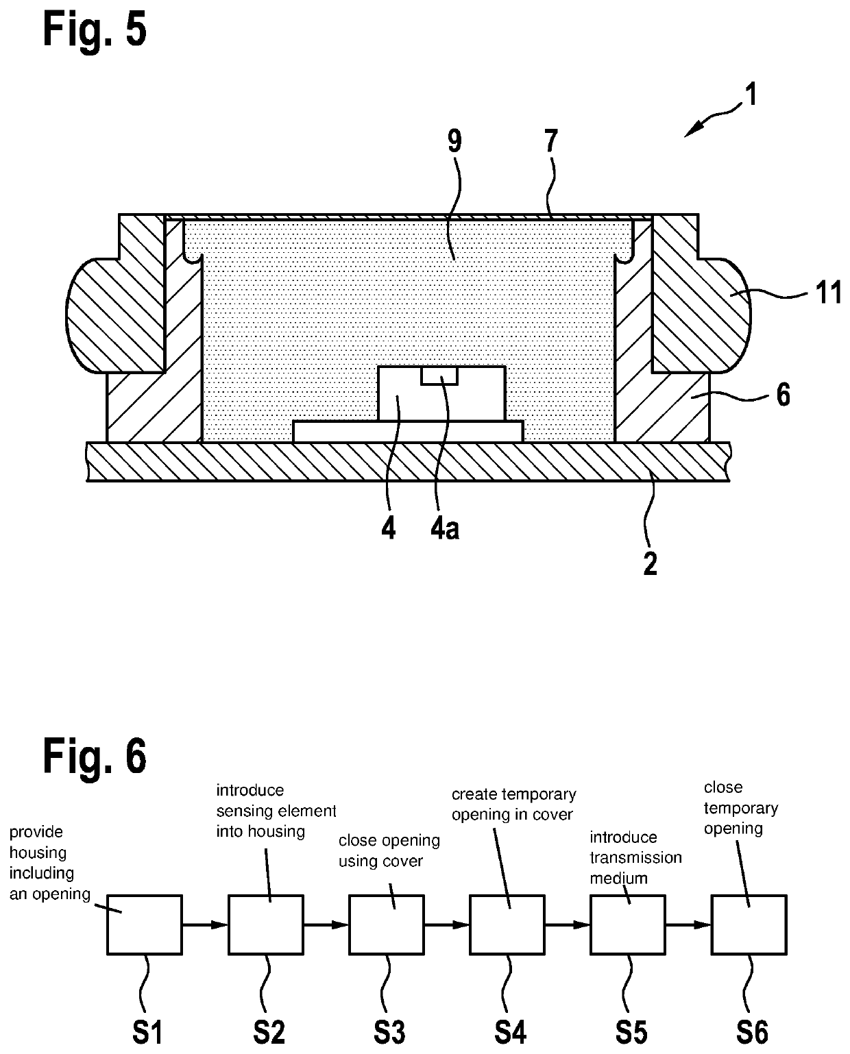
[0046]In detail, FIGS. 1 through 4 each show a sensor 1, which includes a substrate 2 and a rewiring plane (not shown) situated in substrate 2. A chipset 4 including at least one sensing element 4a is situated in a housing, in the form of a sleeve 6, situated on substrate 2. Chipset 4 includes, for example, an evaluation electronics for sensing element 4a. Sensing element 4a may be designed as a MEMS sensing element 4a.

[0047]Sleeve 6 is thus closed on the one side by substrate 2, and on the other side sleeve 6 is closed with the aid of a flexible membrane 7 made up of self-healing ...


PUM


Abstract

A sensor. The sensor include a sensing element for detecting a property and / or a composition of a surrounding medium of the sensor; a transmission medium for transmitting a property and / or a composition of the surroundings medium onto the sensing element, the transmission medium being situated in such a way that the transmission medium is applied to the sensing element; and a cover, which distances the transmission medium from the surrounding medium, the cover being manufactured from a self-healing material, in particular, the cover being designed as a flexible membrane.

Description

FIELD[0001]The present invention relates to a sensor, in particular, a pressure sensor, including a sensing element for detecting a property and / or a composition of a surrounding medium of the sensor.[0002]The present invention furthermore relates to a method for manufacturing a sensor, in particular a pressure sensor, including the steps:[0003]providing a housing including an opening;[0004]introducing the sensing element into the housing; and[0005]closing the opening of the housing with the aid of a cover.BACKGROUND INFORMATION[0006]Although the present invention may, in general, be applied to arbitrary sensors, the present invention is described with respect to sensors in the form of media-robust, encapsulated pressure sensors.[0007]Media-robust, tightly encapsulated pressure sensors or packages, for example according to the oil tank principle, are used when pressures have to be measured in corrosive surroundings, such as for example in hydraulic systems. In the process, the media...

Claims


Application Information

Patent Timeline
IPC IPC(8): G01L19/06G01L9/00
CPCG01L19/0627G01L9/0041G01L19/0645G01L19/142
Inventor NONNENMACHER, DOROTHEEKLETT, GUSTAVKREUTZER, JOACHIMFRIEDL, JOACHIMSODAN, LARS
Owner ROBERT BOSCH GMBH
Why Eureka
Try Eureka