
Front body structure of vehicle

a front body and vehicle technology, applied in the field of front body structure of vehicles, can solve the problems of reducing steering stability, reducing ride comfort for passengers, and unable to form a body frame capable of sufficiently transmitting, so as to achieve efficient transmission of vibration

Active Publication Date: 2020-02-27
MAZDA MOTOR CORP
View PDF0 Cites 3 Cited by
  • Summary
  • Abstract
  • Description
  • Claims
  • Application Information

AI Technical Summary

Benefits of technology

This patent is about improving the structure of the front body of a vehicle to make it stronger and more rigid. It does this by adding link members in the front side frames that connect to reinforcing parts of the suspension housings. This allows the vehicle to better distribute the load and vibration caused by the suspension systems, even when the suspension housings are positioned farthest from the dash panel. Overall, this makes the front body structure of the vehicle stronger and more durable.

Problems solved by technology

Since a relatively large load is likely to act on the suspension housings via the front suspension dampers generally, when the front body is bent and deformed by the load acting via the front suspension dampers, there is a possibility that the steering stability may be reduced and the ride comfort for occupants may be reduced.
However, when the suspension housings are separated from the dash panel toward the vehicle front side, since the cowl box cannot be easily used as a closed cross section member that joins the left and right suspension housings, there is a possibility that it is not possible to form the body frame capable of sufficiently transmitting, to the portion of the body on the rear side of the suspension housings, the load and vibration transmitted from the suspension arm to the sub-frame.

Method used


Image

  • Front body structure of vehicle
  • Front body structure of vehicle
  • Front body structure of vehicle

Examples


Embodiment Construction

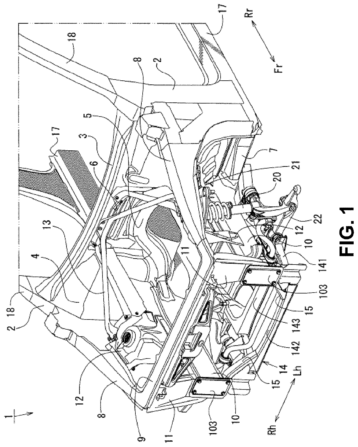
[0046]An embodiment of the present disclosure will be described below with reference to the drawings. A vehicle 1 according to the present embodiment is a vehicle having a ring-shaped structural frame that is substantially ring-shaped in a front body on the vehicle front side of the vehicle interior in which occupants get on and off. The front body structure of the vehicle 1 will be described with reference to FIGS. 1 to 22.

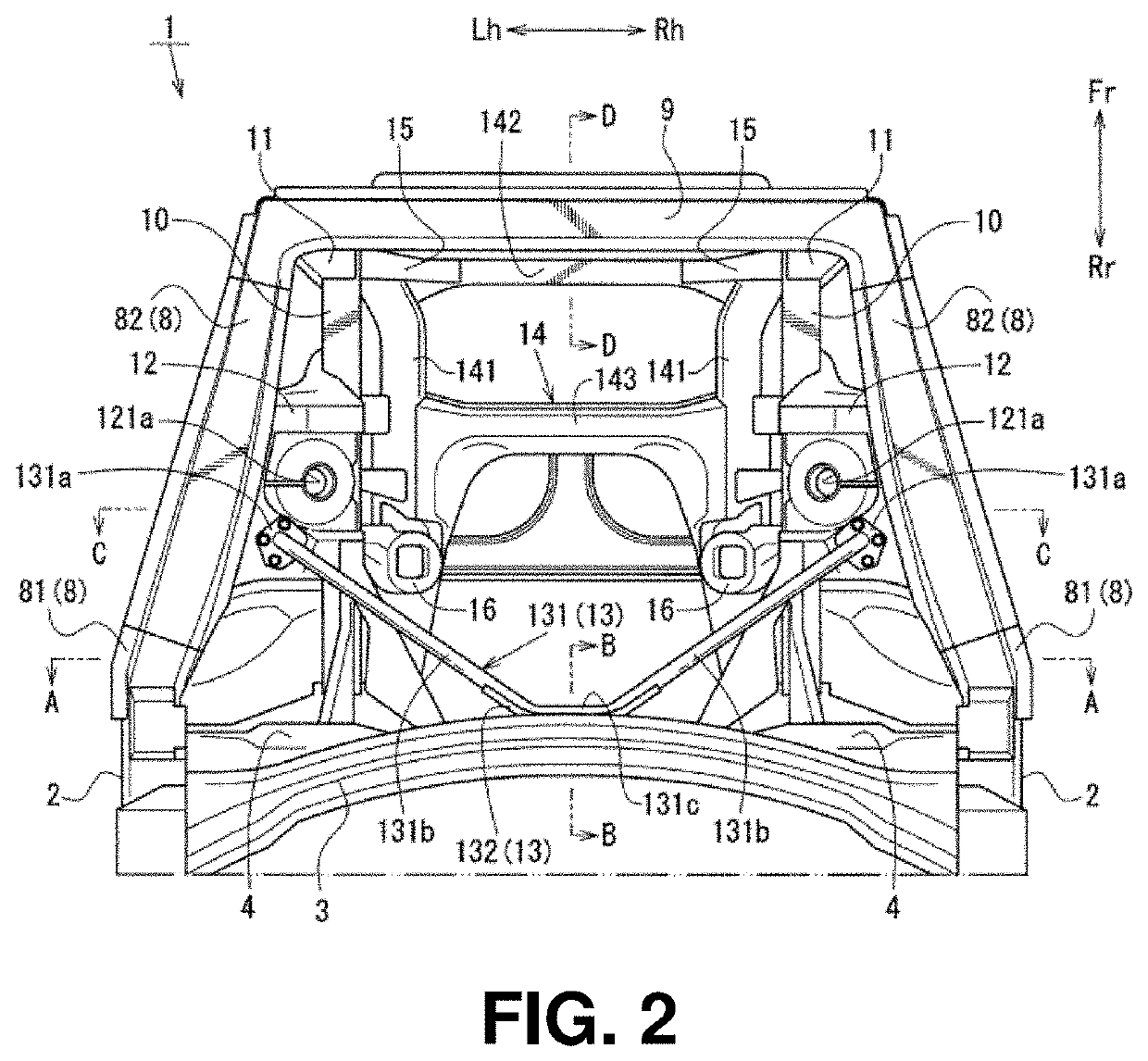
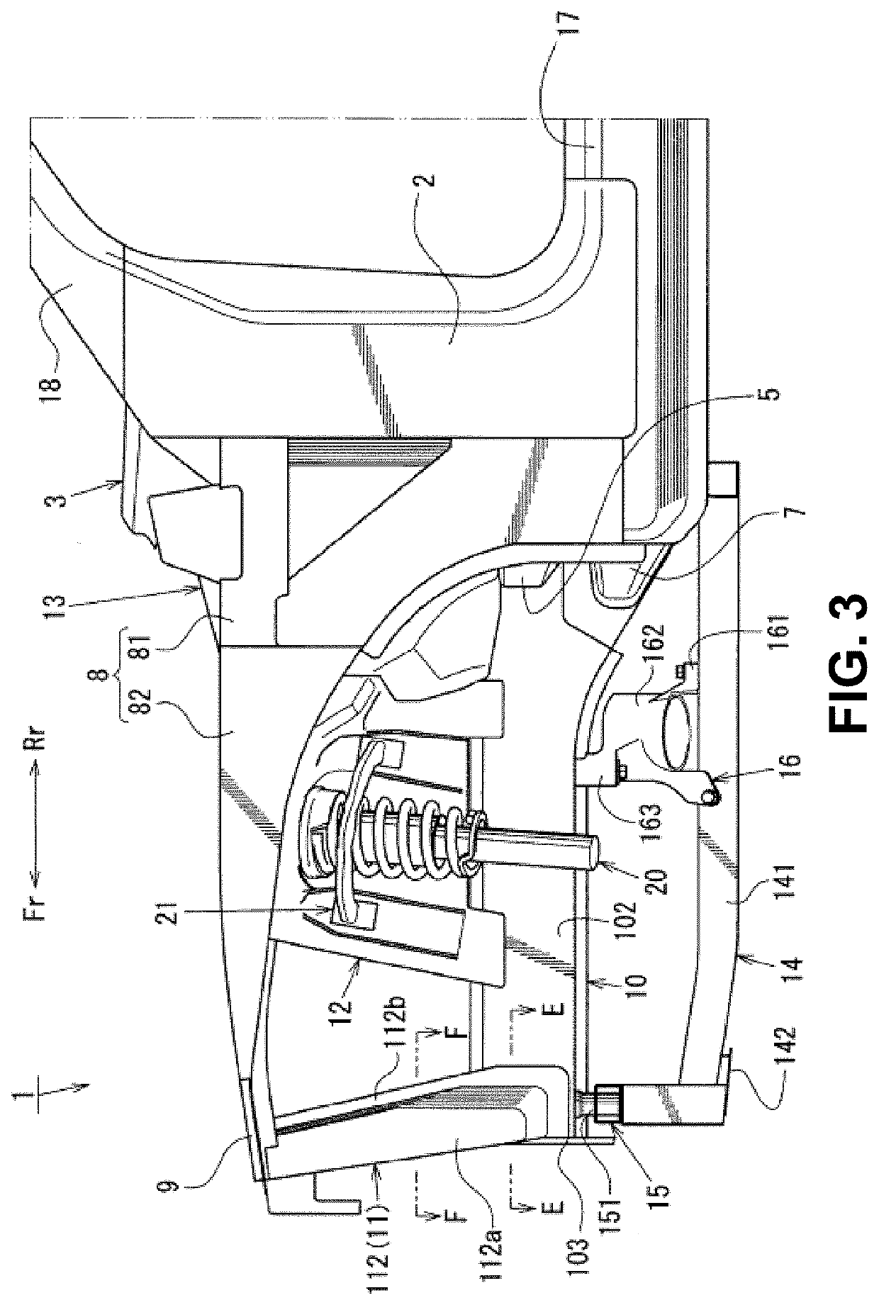
[0047]It should be noted here that FIG. 1 is an appearance perspective view illustrating the front body seen from the upper front of the vehicle, FIG. 2 is a plan view illustrating the front body, FIG. 3 is a left side view illustrating the front body, FIG. 4 is a cross sectional view seen along arrows A-A in FIG. 2, FIG. 5 is a cross sectional view seen along arrows B-B in FIG. 2, FIG. 6 is a cross sectional view seen along arrows C-C in FIG. 2, FIG. 7 is an appearance perspective view illustrating an apron reinforcement lower 822 seen from the upper front of th...


PUM


Abstract

A front body structure of the vehicle includes a pair of left and right rear joint members that join front side frames and the sub-frame in a vehicle up-down direction in substantially the same positions in a vehicle front-rear direction as rear reinforcing parts of the suspension housings, and third link members that separate internal spaces of the front side frames in substantially the same positions in the vehicle front-rear direction as the upper ends of rear joint members. The front body structure further includes a tower bar that joins a cowl box and the rear reinforcing parts of the suspension housings.

Description

BACKGROUNDTechnical Field[0001]The present disclosure relates to a front body structure of a vehicle in which, for example, in front view, a ring-shaped structural frame that is substantially ring-shaped in a vehicle width direction is formed in a front body.Background Art[0002]In a vehicle such as an automobile, front suspension dampers are joined to the frame members of a vehicle body via suspension housings. The front suspension damper suppresses the up-down movement of the vehicle body by, for example, expanding and contracting according to the unevenness of a road surface and improves the ride comfort for occupants.[0003]Since a relatively large load is likely to act on the suspension housings via the front suspension dampers generally, when the front body is bent and deformed by the load acting via the front suspension dampers, there is a possibility that the steering stability may be reduced and the ride comfort for occupants may be reduced.[0004]Accordingly, for example, JP-...

Claims


Application Information

Patent Timeline
Patent Type & Authority Applications(United States)
IPC IPC(8): B62D25/08B62D21/11
CPCB62D25/088B62D21/11B62D25/08B62D25/082
Inventor MATSUOKA, HIROKIWATANABE, SHIGEAKIMATSUOKA, HIDENORIYAMAUCHI, KAZUKI
Owner MAZDA MOTOR CORP
Learn More