Connection terminal

Active Publication Date: 2020-02-27
WAGO VERW GMBH
View PDF0 Cites 2 Cited by
  • Summary
  • Abstract
  • Description
  • Claims
  • Application Information

AI Technical Summary

Benefits of technology

The patent describes a switch mechanism that has a small size and prevents damage to the switch components. The switch has an actuation axis that is angled relative to the direction of the conductor insertion, which allows for efficient use of space and prevents deformation of the switch. It also includes a dividing wall between the actuation and conductor insertion channels, which prevents dirt and foreign particles from entering and improves the overall appearance.

Problems solved by technology

The forces acting on the push button and also the insulating housing can cause the plastic material to deform.
This is especially true because the space available in the area of the clamping spring for accommodating the conductor insertion opening and the push button next to the clamping spring, and thus the available material thickness, is very limited.

Method used


Image

  • Connection terminal
  • Connection terminal
  • Connection terminal

Examples


Embodiment Construction

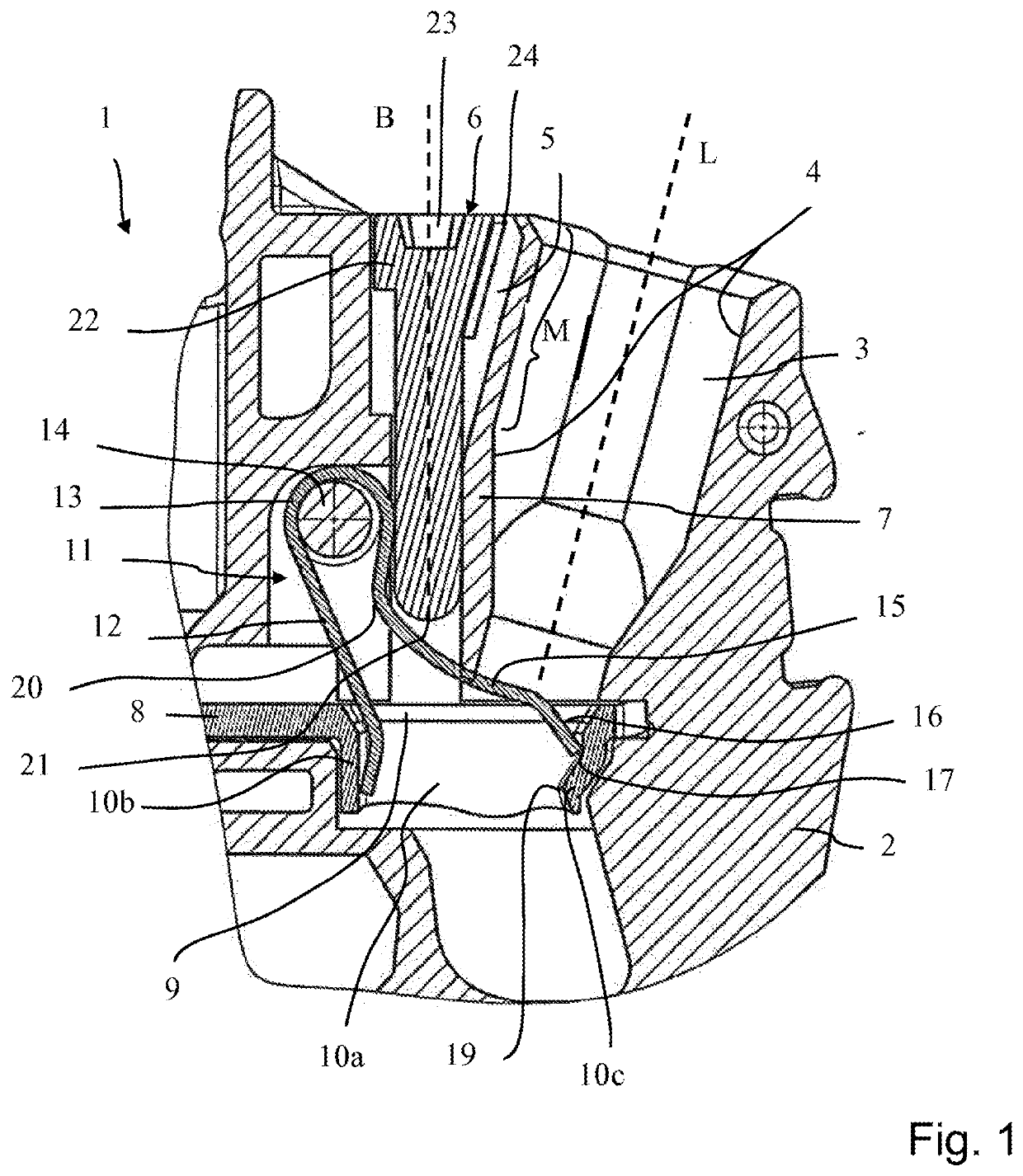
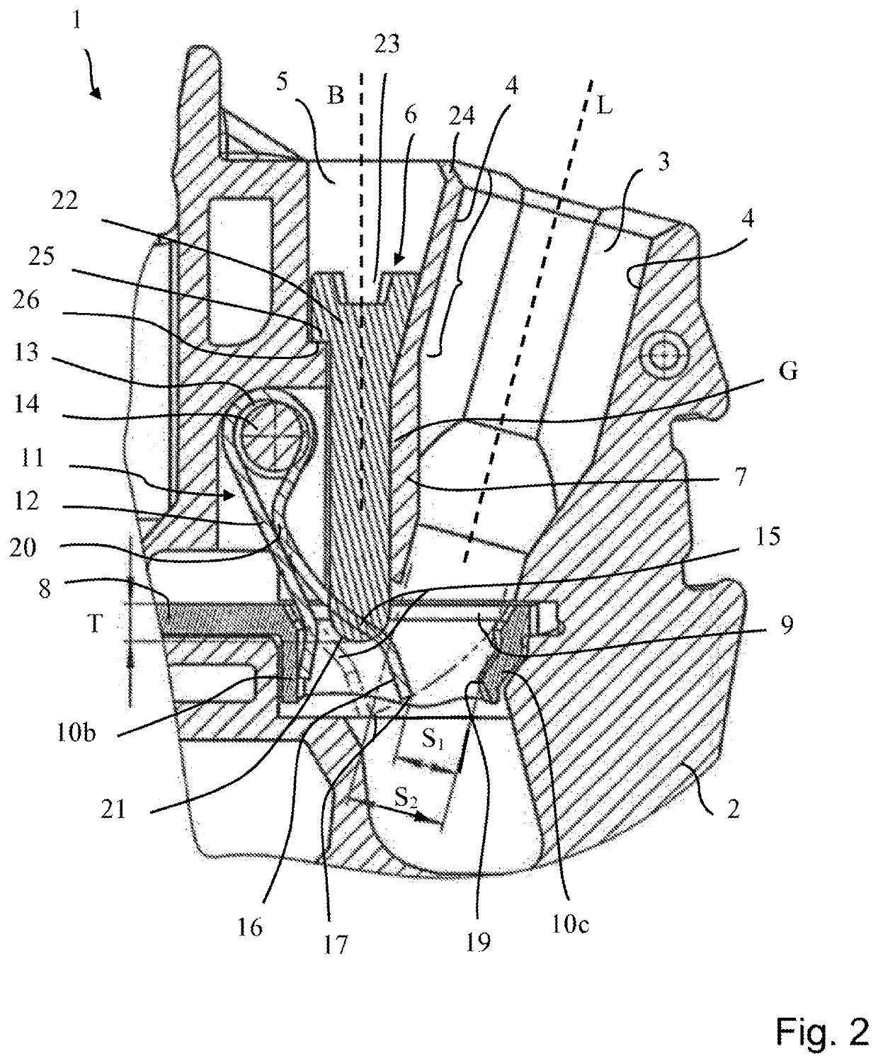
[0047]FIG. 1 shows a sectional view of a connecting terminal 1 with an insulating housing 2. In the illustrated embodiment, the connecting terminal 1 is part of a terminal block, which is shown only as a cutout and can have a plurality of such connecting terminals.

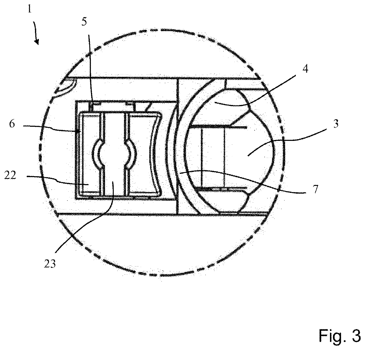
[0048]The insulating housing 2 has a conductor insertion channel 3 which is delimited by circumferential conductor channel walls 4. An actuation channel 5 is arranged next to the conductor insertion channel 3 in which a push button 6 is displaceably mounted. The conductor channel wall 4 of the conductor insertion channel adjoining the actuation channel 5 forms a dividing wall 7 to the actuation channel 5.

[0049]The connecting terminal 1 further has a bus bar 8 with a connection opening 9, which is introduced into the plane which is spanned by the bus bar 8. The connection opening 9 is formed as a material passage having lateral guide walls 10a that project downward from the plane of the bus bar 8 in the insertion direction ...


PUM


Abstract

A connecting terminal having an insulating housing, a conductor insertion channel extending toward a conductor insertion axis with an at least partially circumferential conductor channel wall arranged coaxially to the conductor insertion axis, and an actuation channel disposed adjacent to the conductor insertion channel. A leg spring bent in a U-shape has a contact leg, a clamping leg and a spring bow. A push button is adapted to be received in the actuation channel in a longitudinally displaceable manner. The contact leg is mounted on the bus bar, and a clamping edge of the clamping leg forms a spring clamp connection with a contact region of the bus bar for clamping an electrical conductor inserted in the conductor insertion channel. An actuation axis defined by a displacement direction of the push button and the conductor insertion axis are aligned with each other at an angle of 5° to 30°.

Description

[0001]This nonprovisional application is a continuation of International Application No. PCT / EP2018 / 060594, which was filed on Apr. 25, 2018, and which claims priority to German Patent Application No. 10 2017 109 694.9, which was filed in Germany on May 5, 2017, and which are both herein incorporated by reference.BACKGROUND OF THE INVENTIONField of the Invention[0002]The present invention relates to a connecting terminal.Description of the Background Art[0003]DE 10 2013 111 574 A1, which corresponds to U.S. Pat. No. 9,614,301, which is incorporated herein by reference, shows a spring clamp connection for clamping electrical conductors with a push button that is displaceably received in the insulating housing. The push button has an actuation surface for engagement with the clamping leg of the clamping spring, such that the push button is guided along the clamping leg. A projecting lug of the push button sticks out into the mouth of the conductor insertion opening and forms part of t...

Claims


Application Information

Patent Timeline
IPC IPC(8): H01R4/48H01R9/22H01R9/24
CPCH01R9/2408H01R4/4845H01R9/223H01R4/4836H01R4/489H01R4/48185H01R4/48455H01R4/48365H01R4/48
Inventor KOELLMANN, HANS-JOSEFHARTMANN
Owner WAGO VERW GMBH
Why Eureka
Try Eureka