

Imaging lens
- Summary
- Abstract
- Description
- Claims
- Application Information
AI Technical Summary
Benefits of technology
Problems solved by technology
Method used
Image

Examples
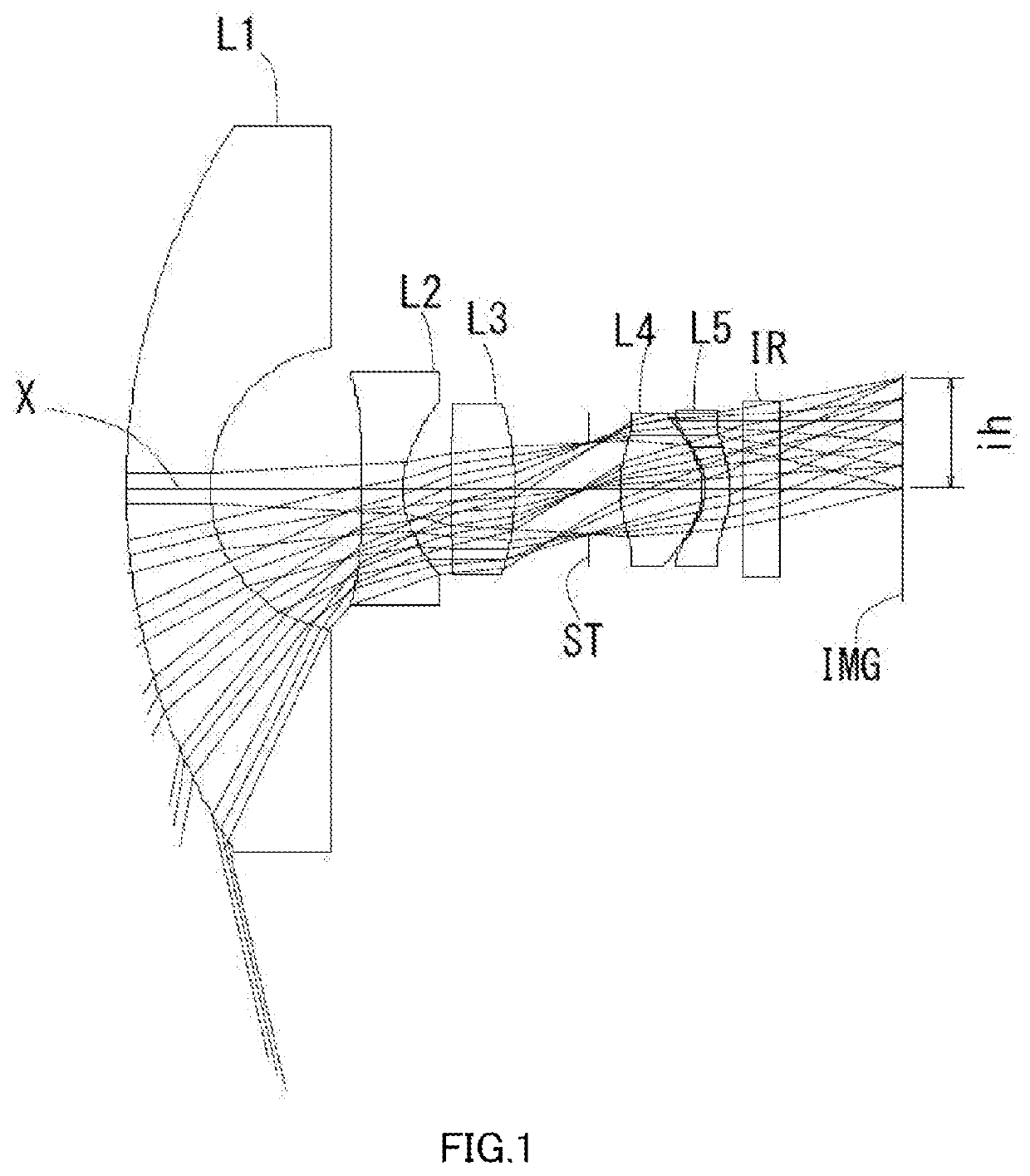
example 1
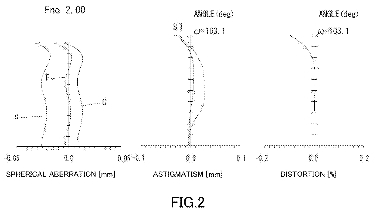
[0086]The basic lens data is shown below in Table 1.
TABLE 1Example 1Unit mmf = 1.08ih = 1.85Fno = 2.0TTL = 12.70ω (°) = 103.1Surface DataSurfaceCurvatureSurfaceRefractiveAbbeNumber iRadius rDistance dindex NdNumber vd(Object)InfinityInfinity 110.94731.39481.77349.61 (νd1) 22.37562.5027 3*28.00000.70001.53556.11 (νd2) 4*1.56660.7921 530.00001.06961.92123.95 (νd3) 6−4.63001.2183 7 (Stop)Infinity0.5329 8*2.54331.35371.53556.11 (νd4) 9*−1.02710.057410*−0.85330.40001.66120.37 (νd5)11*−1.55670.200012Infinity0.61001.51764.1713Infinity2.0724Image PlaneInfinityConstituent Lens DataLensStart SurfaceFocal Length11−4.22723−3.132354.420481.577510−3.693Aspheric Surface DataThird SurfaceFourth SurfaceEighth SurfaceNinth SurfaceTenth SurfaceEleventh Surfacek0.000000E+000.000000E+000.000000E+00−5.000000E−01−9.450000E−01−7.536689E−01A4−3.184689E−02−5.726524E−02−1.579708E−021.950291E−012.371644E−011.052116E−01A67.060004E−039.183170E−038.343853E−02−1.188862E−01−2.059529E−01−1.573902E−02A8−1.015862E−03−...
example 2
[0089]The basic lens data is shown below in Table 2.
TABLE 2Example 2Unit mmf = 1.08ih = 1.85Fno = 2.0TTL = 12.70ω (°) = 103.6Surface DataSurfaceCurvatureSurfaceRefractiveAbbeNumber iRadius rDistance dIndex NdNumber vd(Object)InfinityInfinity 110.34621.62071.77349.61 (νd1) 22.40612.4913 3*28.00000.70001.53556.11 (νd2) 4*1.48190.7262 515.00001.13661.92320.87 (νd3) 6−5.99760.9787 7 (Stop)Infinity0.5262 8*2.22161.54201.53556.11 (νd4) 9*−1.00570.050010*−0.89510.40001.66120.37 (νd5)11*−1.68300.200012Infinity0.61001.51764.1713Infinity1.9215Image PlaneInfinityConstituent Lens DataLensStart SurfaceFocal Length11−4.45523−2.953354.766481.553510−3.626Aspheric Surface DataThird SurfaceFourth SurfaceEighth SurfaceNinth SurfaceTenth SurfaceEleventh Surfacek0.000000E+000.000000E+000.000000E+00−6.000000E−01−9.091390E−01−6.262823E−01A4−4.378410E−02−8.783401E−02−8.453853E−031.606601E−011.678151E−018.206727E−02A61.628357E−026.430488E−021.065343E−027.718018E−024.734845E−02−8.198620E−03A8−5.139827E−03−1....
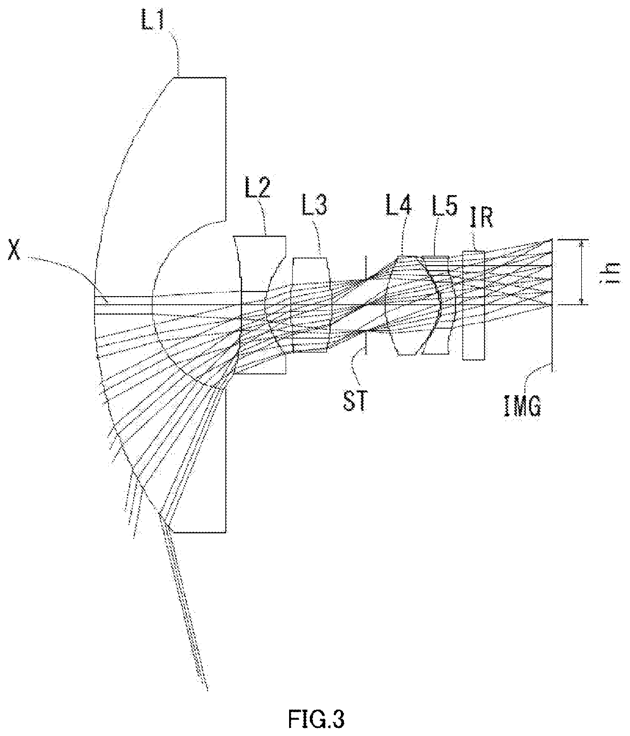
example 3
[0092]The basic lens data is shown below in Table 3.
TABLE 3Example 3Unit mmf = 1.09ih = 1.85Fno = 2.0TTL = 12.69ω (°) = 103.0Surface DataSurfaceCurvatureSurfaceRefractiveAbbeNumber iRadius rDistance dindex NdNumber vd(Object)InfinityInfinity 110.86931.57841.77349.61 (νd1) 22.33212.4507 3*28.00000.70001.53556.11 (νd2) 4*1.49450.7363 515.00001.17711.92123.95 (νd3) 6−5.04291.0395 7 (Stop)Infinity0.5554 8*2.45661.42231.53556.11 (νd4) 9*−0.97950.050010*−0.86970.40001.66120.37 (νd5)11*−1.69340.200012Infinity0.61001.51764.1713Infinity1.9801Image PlaneInfinityConstituent Lens DataLensStart SurfaceFocal Length11−4.18023−2.980354.216481.530510−3.355Aspheric Surface DataThird SurfaceFourth SurfaceEighth SurfaceNinth SurfaceTenth SurfaceEleventh Surfacek0.000000E+000.000000E+000.000000E+00−6.000000E−01−9.240279E−01−5.971269E−01A4−3.911302E−02−7.765487E−022.245820E−031.951324E−011.980397E−018.490239E−02A61.041511E−024.429496E−02−1.320357E−02−7.969125E−02−1.003997E−01−1.517091E−02A8−1.415962E−03−...
PUM
 Abstract
Description
Claims
Application Information