Lighting device and display device provided with the same
a technology of display device and light source, which is applied in the direction of instruments, non-linear optics, optics, etc., can solve the problems of severe uneven luminance of backlight unit b>6/b>, defects in conventional direct-lit lighting devices, and uneven luminance, so as to prevent uneven luminance
- Summary
- Abstract
- Description
- Claims
- Application Information
AI Technical Summary
Benefits of technology
Problems solved by technology
Method used
Image
Examples
first embodiment
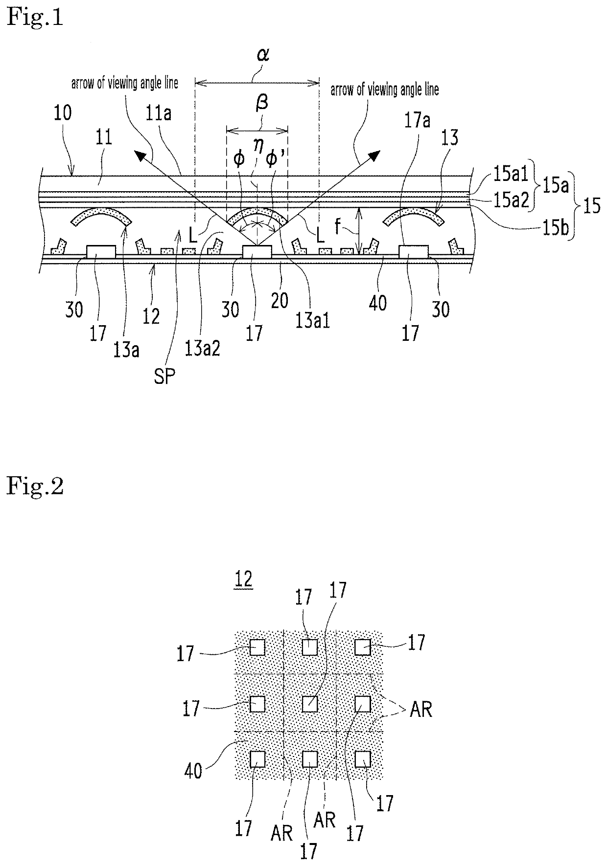
[0048]FIG. 1 is a partial schematic sectional view of a liquid crystal display device 10 provided with an example of a backlight unit 12 according to First Embodiment. Signs φ, φ′ in FIG. 1 indicate viewing angles. FIG. 2 is a schematic plan view of the backlight unit 12 shown in FIG. 1, with an optical member group 15 removed. Dashed lines in FIG. 2 define local dimming division areas AR. FIG. 3 is a schematic plan view of a zone corresponding to an LED 17, as an example of a reflector pattern 13a of a reflector 13, in the backlight unit 12 shown in FIG. 1.
[0049]As shown in FIG. 1, the liquid crystal display device 10 (an example of the display device) is provided with a liquid crystal panel 11 (an example of the display element) and a backlight unit 12 (an example of the lighting device) configured to illuminate the liquid crystal panel 11 from behind. The shape of the liquid crystal display device 10 is not particularly limited, and may be rectangular or square.
[0050]The liquid c...
second embodiment
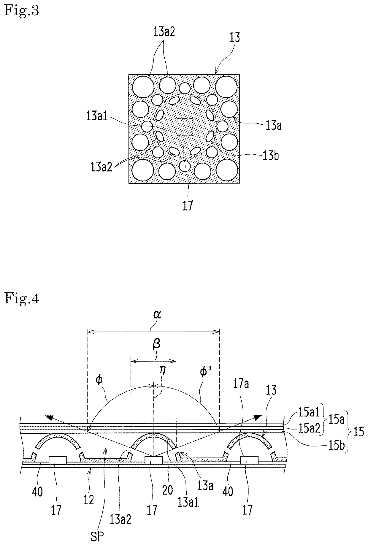
[0075]FIG. 5 is a partial schematic sectional view of an example of the backlight unit 12 according to Second Embodiment. FIG. 6 is a partial schematic plan view of an example of the reflector pattern 13a in the reflector 13 shown in FIG. 5.
[0076]The backlight unit 12 according to Second Embodiment is substantially identical to the backlight unit 12 according to First Embodiment, except that the solid portions in the reflector 13 have a frustum-like shape.
[0077]To be specific, the backlight units 12 according to First and Second Embodiments are basically identical but are different in the following respect. In Second Embodiment, the reflector 13 is bent such that a side surface δ in each solid portion is nearly vertical to the substrate surface of the LED board 20 and such that the other surface in each solid portion is parallel or substantially parallel to the substrate surface of the LED board 20.
[0078]Each solid portion in the reflector 13 has, ideally but not necessarily, a semi...
first embodiment and second embodiment
Notes on First Embodiment and Second Embodiment
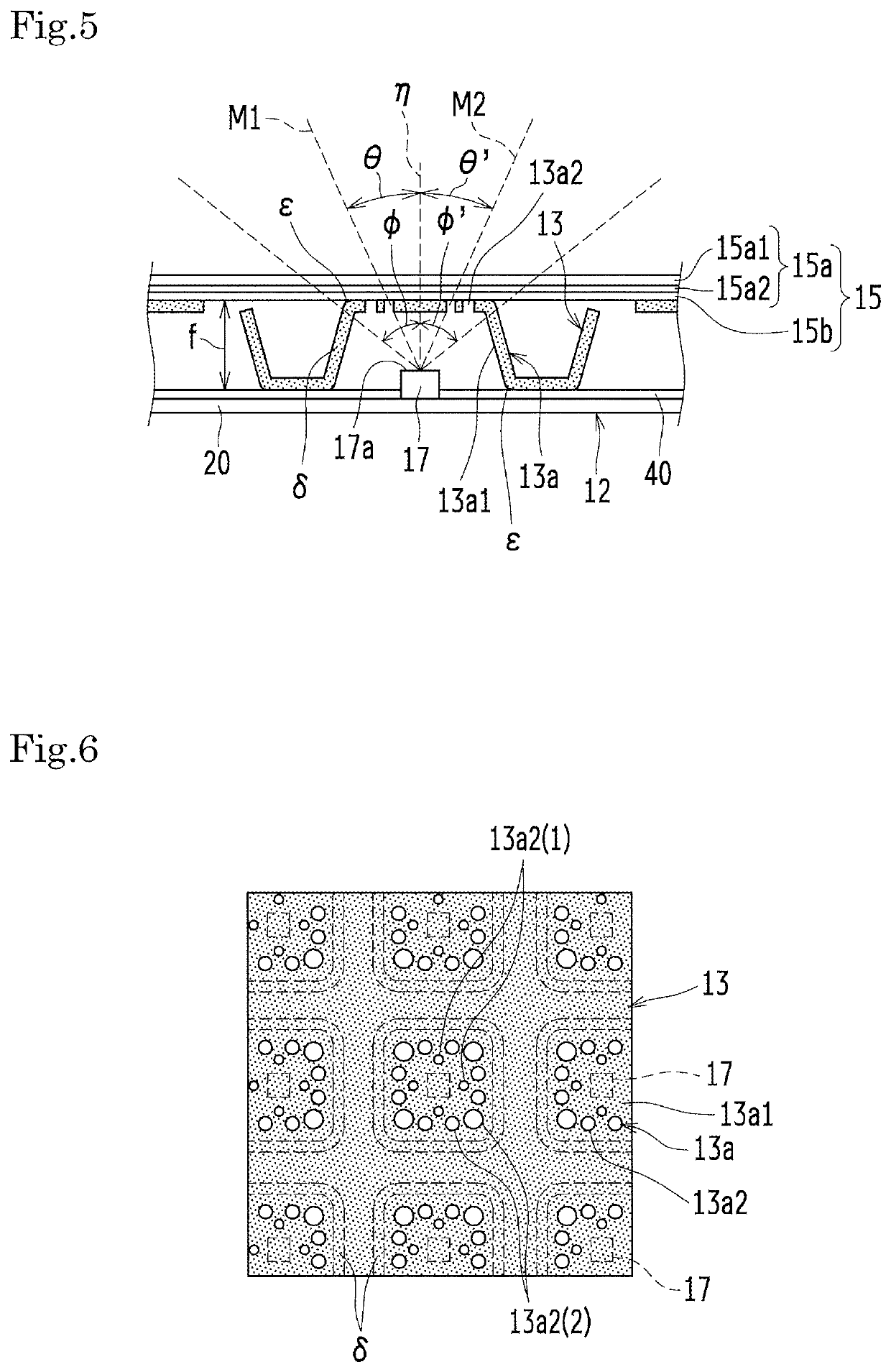
[0087]FIG. 7 is a schematic sectional view showing another example of the backlight unit 12 according to First Embodiment. For example, to prevent uneven luminance in the backlight unit 12 at the viewing angles φ, φ′ of 45° or less, the reflector pattern 13a is designed to make the LEDs 17 directly invisible at the viewing angles φ, φ′ of 45° or less. Specifically, in the case where the range of viewing angle lines is equal to the covered zone ß, the light the transmission parts 13a2 (holes) are not provided in the reflector pattern 13a within the range of viewing angle lines (the covered zone ß) drawn from the center of the light emitting surface 17a (the emission point) of each LED 17 at the viewing angles φ, φ′ of 45°. Referring to the reflector pattern 13a in FIG. 7, no light transmission part 13a2 is provided in the reflector pattern 13a within the range of viewing angle lines (the covered zone ß). FIG. 7 is a sectional view of the...
PUM
 Abstract
Description
Claims
Application Information
 - R&D
- Intellectual Property
- Life Sciences
- Materials
- Tech Scout
- Unparalleled Data Quality
- Higher Quality Content
- 60% Fewer Hallucinations
Browse by: Latest US Patents, China's latest patents, Technical Efficacy Thesaurus, Application Domain, Technology Topic, Popular Technical Reports.
© 2025 PatSnap. All rights reserved.Legal|Privacy policy|Modern Slavery Act Transparency Statement|Sitemap|About US| Contact US: help@patsnap.com


