Distributed Deadblow Tools

a technology of dead blowing tools and dead blowing, which is applied in the direction of hand hammers, portable percusive tools, metal working devices, etc., can solve the problem of less efficient force transfer

Inactive Publication Date: 2020-03-12
DONER TODD HENRY
View PDF0 Cites 6 Cited by
  • Summary
  • Abstract
  • Description
  • Claims
  • Application Information

AI Technical Summary

Benefits of technology

[0012]The present invention directly addresses each of the prior-art deadblow tool limitations mentioned above by adding a plurality of distributed chambers, each tunable by location, orientation, shape, and size, as well as, tunable by the weight and volume of the freely moveable material inserted therein. Collectively, these tuning options enable some variation and control in regard to the movement of mass in relation to each chamber's counterstrike or blow as far as when, where, and by how much. Insertable chambers and tool construction methods are also provided.

Problems solved by technology

Prior-Art deadblow tools are limited in several ways:no controls to balance the freely moveable material within the tool,leaving the user to physically compensate;no controls to eliminate freely moveable material from pooling or settling in one area of the chamber, requiring more effort to move the depth of freely moveable material as is evident when striking with a deadblow tool horizontally;no control to balance the strike across the struck surface resulting in less efficient force transfer as freely moveable material can strike more in one area than another, and in varying amounts, on each strike resulting in lost energy as the freely moveable material is forced to spread out when mounded higher than the freely moveable material in the rest of the chamber; andno controls to maintain balance while the tool is in motion.

Method used


Image

  • Distributed Deadblow Tools
  • Distributed Deadblow Tools
  • Distributed Deadblow Tools

Examples


Embodiment Construction

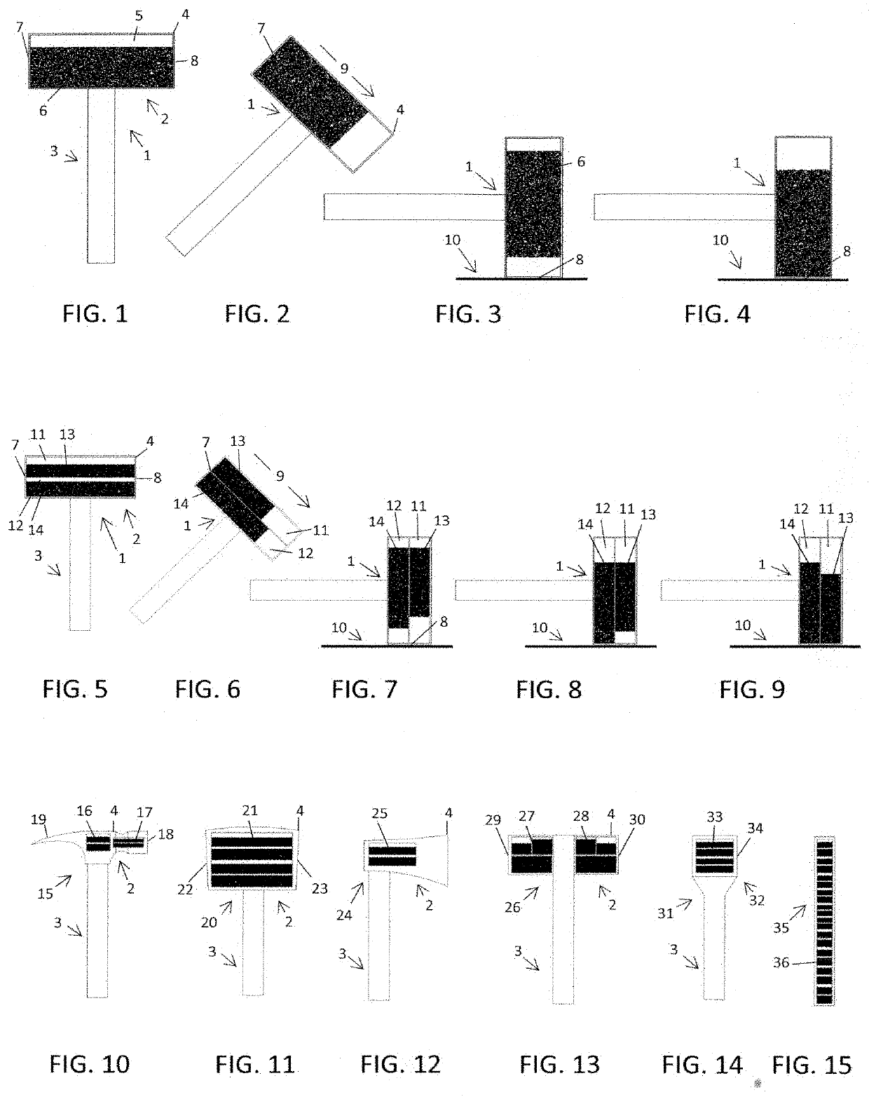
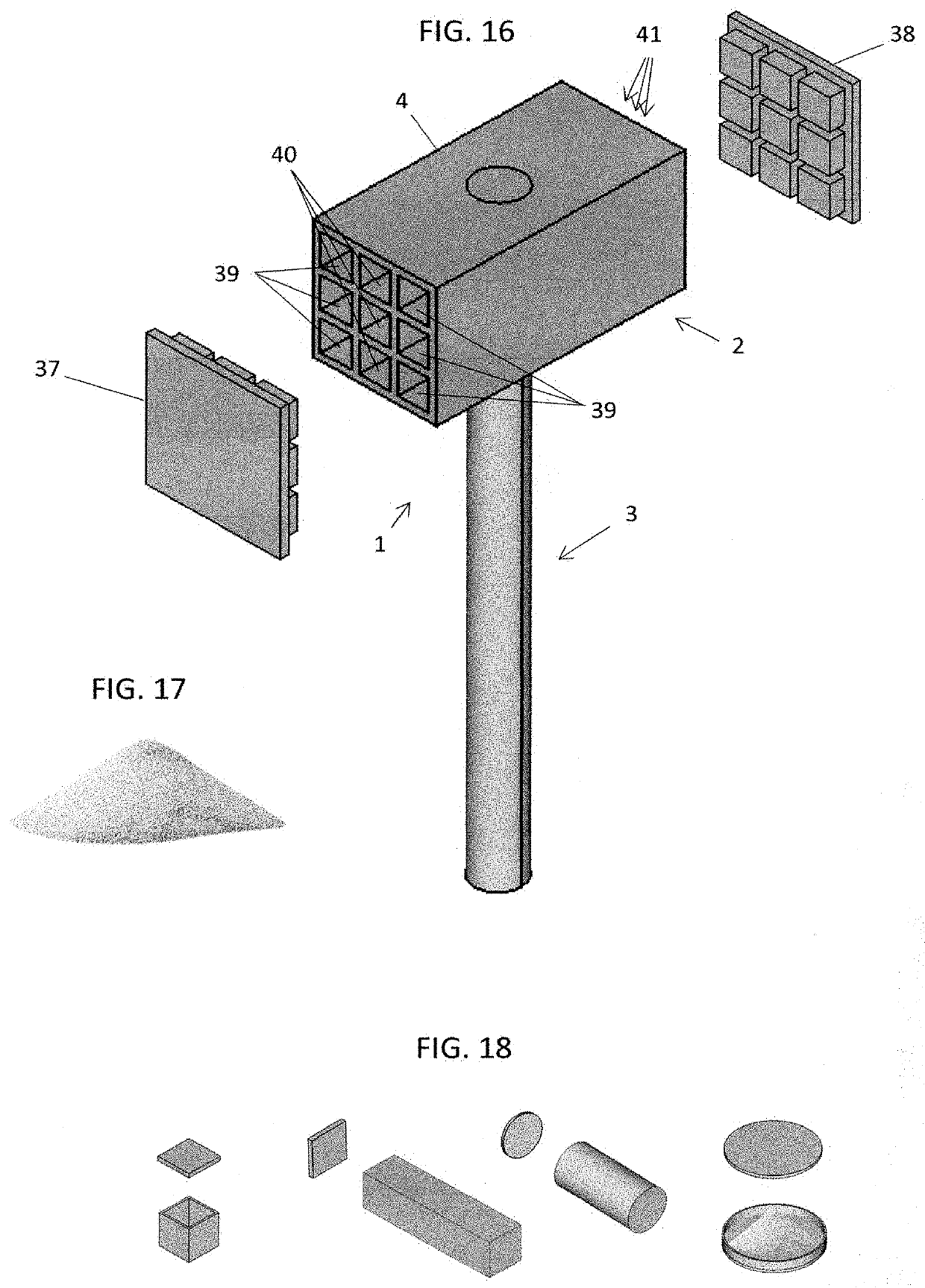
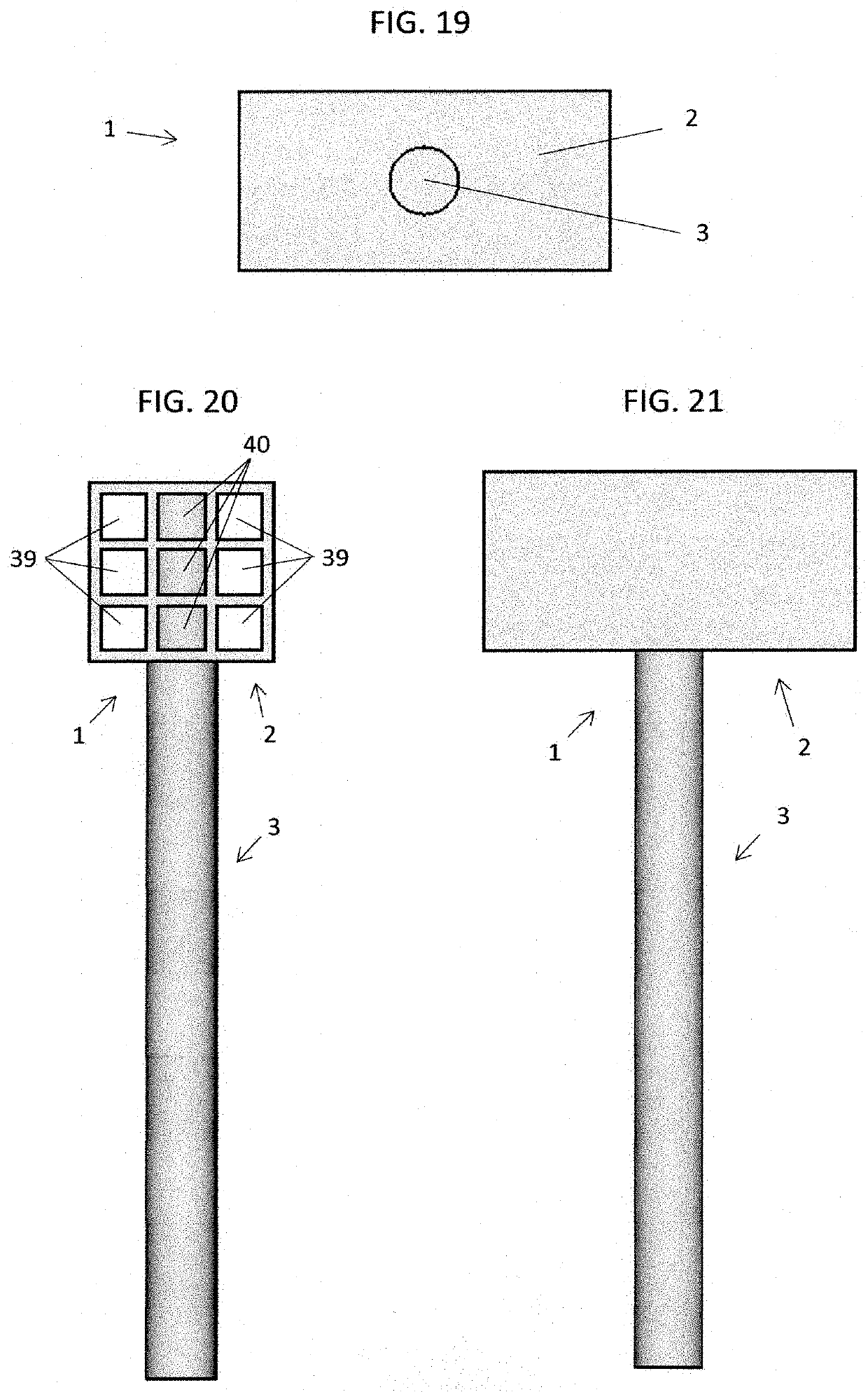
[0040]The below description and attached drawings are offered to explain the invention in detail and are not intended to describe or illustrate the only way the invention may be configured, constructed, or used. The invention can be applied to numerous striking tools regardless of tool head shape, like flat, round, ball pein, cross pein, straight pein, blade, magnet nail holders, and claw, as well as size, like tiny jewelry repair hammers, giant sledge hammers, hatchets, and axes, and various materials, like steel, brass, bronze, copper, aluminum, lead, rubber, wood, plastic, and nylon. Furthermore, the chambers can be constructed in numerous ways as well, such as molded, machined, and fabricated, in different shapes, sizes, textures, as well as different shapes at the ends, like a stair-step that would provide similar effects to having separate chambers of differing lengths. And finally, the selection of freely moveable material has many options as well, such as sand, gravel, shot,...


PUM


Abstract

A deadblow tool, comprising a head with one or more striking surfaces; a handle joined to or molded as one with the head; a plurality of hollow chambers within the tool embodiment; a plurality of freely moveable material partially filling the hollow chambers; and an embodiment in the form of a hammer, mallet, axe, or annular maul. The tool has hollow chambers created as part of the tool embodiment or created separately as chamber cartridges to be inserted into the tool embodiment. The hollow chambers and chamber cartridges vary in size and shape and the freely moveable material varies in density and volume to accommodate mass distribution and the adjustments thereof provide facilitation to further tune the tool balance and strike performance. Construction methods of chamber cartridges and deadblow handles, hammers, mallets, axes, and mauls are also provided.

Description

CROSS-REFERENCE TO RELATED APPLICATIONS[0001]N / ABACKGROUND OF THE INVENTION1. Field of the Invention[0002]The present invention is in the field of striking hand tools including hammers, mallets, axes, and annular mauls and pertains particularly to balance and antirecoil characteristics of deadblow tools.2. Description of Related Art[0003]Deadblow (aka dead-blow, non-recoil, anti-recoil, no-bounce, or recoilless) tools, such as hammers, mallets, axes, and mauls, are well known to significantly reduce rebound by distributing the strike over time; thereby reducing the peak force and absorbing a significant amount of the recoil that would otherwise be returned through rebound to the user's hands and arms. Deadblow tools are used in many industries, including but not limited to, auto repair, hydraulic maintenance, aerospace work, telecommunications cable work, woodworking, woodcarving, metalworking, and surgical procedures.[0004]Prior-art deadblow tools are comprised of a single hollow c...

Claims


Application Information

Patent Timeline
Patent Type & Authority Applications(United States)
IPC IPC(8): B25D1/12B25D1/14B26B23/00
CPCB25D1/12B26B23/00B25D1/04B25D1/14B25D2250/105B25D2250/391
Inventor DONER, TODD HENRY
Owner DONER TODD HENRY
Why Eureka
Try Eureka