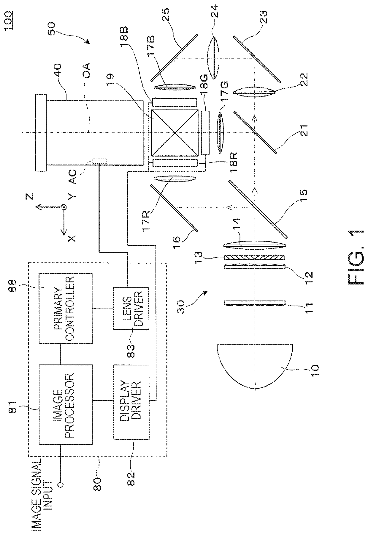
Projection system and projector
- Summary
- Abstract
- Description
- Claims
- Application Information
AI Technical Summary
Benefits of technology
Problems solved by technology
Method used
Image


Examples
example 1
[0054]Table 1 shown below shows data on the lens surfaces in Example 1.
TABLE 1Lens dataSurfacenumberRDndνd 1(*)−32.3883.801.5094255.88 2(*)−36.840.40 385.7532.001.4970081.54 423.29512.30 5−32.2771.201.4970081.54 6176.971variable 7−19221.19.221.8340037.16 8−29.1771.301.8466623.78 9−87.5950.201070.264.561.8466623.7811−400.911variable1263.8475.671.7725049.6013−41.4751.101.7847026.2914−346.683variable15−46.3381.001.7173629.521653.398variable17(*)−113.8844.361.7432049.2918(*)−27.087variable19−27.4321.2 1.6989530.132033.4818.251.4970081.5421−36.3430.202299.625.051.8080922.7623−77.605variable24268.0255.981.4970081.5425−42.4795.0026infinity28.82 1.5163064.1427infinity 6.685Surfacenumber121718k−7.520−8 .149−1.8400.592A4 1.884E−05 1.867E−05−1.821E−05−4.586E−06A6−3.042E−08−3.362E−08−1.084E−08−9.462E−09A8 4.141E−11 4.668E−11−8.305E−10−3.565E−10A10−3.542E−14−4.293E−14 2.863E−14−1.821E−12A12 2.387E−17 4.143E−17 1.062E−14 2.926E−14A14−5.701E−21−1.671E−20−2.200E−16−1.729E−16(*)Data on aspheric sur...
example 2
[0069]Table 4 shown below shows data on the lens surfaces in Example 2.
TABLE 4Lens dataSurfacenumberRDndνd 1(*)−30.9363.801.5094255.88 2(*)−35.9090.40 381.7002.001.4970081.54 422.98312.40 5−31.2181.201.4970081.54 6118.382variable 7176.01310.15 1.8340037.16 8−29.8941.301.8466623.78 9−103.4710.201083.2764.321.8466623.7811−298.531variable1263.5555.581.7725049.6013−43.0251.101.7282528.46141804.821variable15−38.3441.001.7618226.521675.191variable17(*)−217.0354.361.7432049.2918(*)−29.418variable19−32.0191.201.6989530.132034.7807.551.4970081.5421−41.7690.202287.9384.851.8080922.7623−86.874variable24170.5375.171.5952267.7425−55.3305.0026infinity28.82 1.5163064.1427infinity6.48Surfacenumber121718K−7.430−8.549−2.0000.552A4 1.814E−05 1.763E−05−1.502E−05−4.714E−06A6−3.054E−08−3.378E−08−9.047E−10−3.490E−09A8 4.119E−11 4.712E−11−8.308E−10−4.130E−10A10−3.544E−14−4.347E−14 2.517E−12−1.756E−12A12 2.399E−17 3.962E−17 1.440E−14 3.115E−14A14−6.586E−21−1.602E−20−2.073E−16−1.736E−16(*)Data on aspheric s...
PUM
 Abstract
Description
Claims
Application Information