Printing apparatus, printing system, printing method

Inactive Publication Date: 2020-03-26
DAINIPPON SCREEN MTG CO LTD
View PDF0 Cites 0 Cited by
  • Summary
  • Abstract
  • Description
  • Claims
  • Application Information

AI Technical Summary

Benefits of technology

The present invention aims to prevent ink from overflowing into the negative pressure applying part during power failures or circulation pump stoppages. The invention provides a technology to quickly cancel the pressure difference between the supply tank and the recovery tank, suppressing the inflow of ink. This helps to protect the invention's components and prevents ink overflow.

Problems solved by technology

When the circulation pump is stopped due to a power failure, however, the flow back of the ink from the recovery tank to the supply tank is stopped.
At that time, there are some cases where the ink overflows from the recovery tank into the negative pressure tank since the ink has flowed from the supply tank into the recovery tank beyond the capacity of the recovery tank.

Method used


Image

  • Printing apparatus, printing system, printing method
  • Printing apparatus, printing system, printing method
  • Printing apparatus, printing system, printing method

Examples


Embodiment Construction

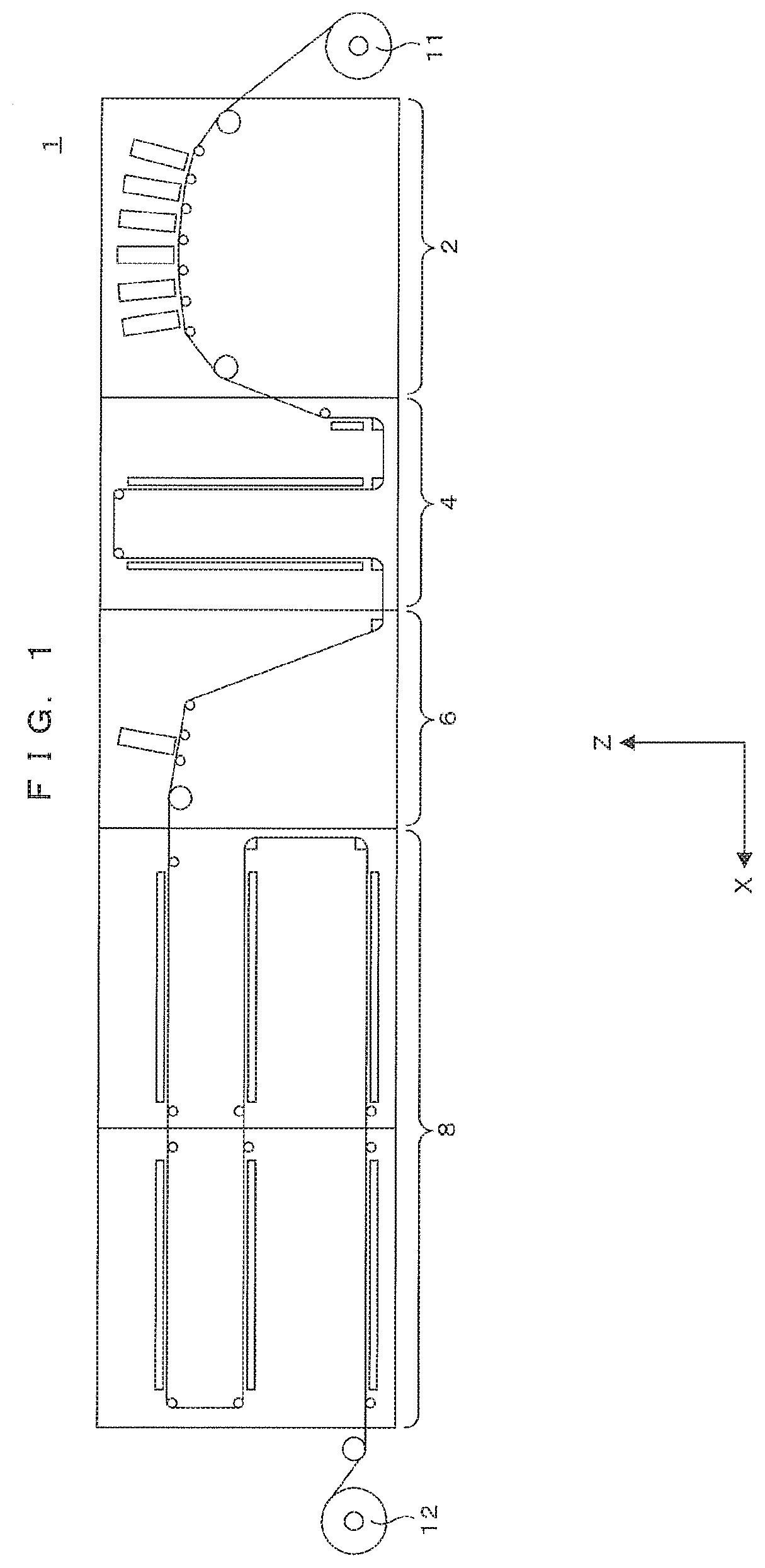
[0015]FIG. 1 is a front elevational view schematically showing one example of a printing system in accordance with the present invention. In FIG. 1 and the following figures, a horizontal direction X and a vertical direction Z are shown as appropriate. As shown in FIG. 1, a printing system 1 includes a configuration in which a prestage printer 2, a prestage dryer 4, a post-stage printer 6, and a post-stage dryer 8 which have the same height as one another are arranged in this order in the horizontal direction X. This printing system 1 transfers a printing medium M from a unwind roll 11 to a rewind roll 12 in a roll-to-roll process while causing the prestage dryer 4 to dry the printing medium M printed by the prestage printer 2 and causing the post-stage dryer 8 to dry the printing medium M printed by the post-stage printer 6. Herein, an exemplary case where printing is performed on the printing medium M which is a transparent film by using water-based ink will be shown. Further, her...


PUM


Abstract

A printing apparatus, comprises: a discharge head; a recovery tank that stores ink recovered from the discharge head; a supply tank that stores ink to be supplied to the discharge head; a circulation pump that performs an ink circulation operation of circulating ink in a circulation path that returns to the recovery tank after reaching the discharge head from the recovery tank via the supply tank; a first negative pressure applying part configured to apply a negative pressure to the supply tank; a second negative pressure applying part configured to apply a negative pressure to the recovery tank; a first solenoid valve to cut off the supply tank and the recovery tank when being energized and cause the supply tank and the recovery tank to communicate when not being energized; and a power supply part configured to supply electric power to the circulation pump and the first solenoid valve.

Description

CROSS REFERENCE TO RELATED APPLICATION[0001]The disclosure of Japanese Patent Application No. 2018-177462 filed on Sep. 21, 2018 including specification, drawings and claims is incorporated herein by reference in its entirety.BACKGROUND OF THE INVENTION1. Field of the Invention[0002]The present invention relates to a technology for circularly supplying ink to a discharge head which discharges the ink from a nozzle.2. Description of the Related Art[0003]In a printer disclosed in Japanese Patent Application Laid Open Gazette No. 2014-200969 (Patent Document 1), a supply tank (pressurizing tank) for supplying ink to a discharge head by using a water head difference and a recovery tank (negative pressure tank) for recovering ink from the discharge head are provided, and the ink is circularly supplied to the discharge head by a circulation pump disposed between these tanks.SUMMARY OF THE INVENTION[0004]In the above printer, the pressure inside the recovery tank is lower than that inside ...

Claims


Application Information

Patent Timeline
IPC IPC(8): B41J2/175
CPCB41J2/17566B41J2/17596B41J2/01B41J2/18B41J2/17506B41J11/002B41J2/175B41J2/185B41J2/17563
Inventor MUTO, SHOGO
Owner DAINIPPON SCREEN MTG CO LTD
Why Eureka
Try Eureka