Acoustic chambers damped with side-branch resonators, and related systems and methods

a technology of sidebranch resonators and acoustic chambers, which is applied in the direction of transducer casings/cabinets/supports, electrical transducers, earpieces/earphone manufacture/assembly, etc., can solve the problems of many electronic devices that do not incorporate conventional acoustic radiators and acoustic chambers, and electronic devices do not provide an audio experience to users on par with that provided

Active Publication Date: 2020-03-26
APPLE INC
View PDF7 Cites 9 Cited by
  • Summary
  • Abstract
  • Description
  • Claims
  • Application Information

AI Technical Summary

Benefits of technology

[0014]According to another aspect, electronic devices are described. An electronic device can include an electro-acoustic transducer and circuitry to drive the electro-acoustic transducer to emit sound over a selected frequency bandwidth. For example, such circuitry can include a processor and a memory. The memory can contain instructions that, when executed by the processor, cause the electronic device to drive the electro-acoustic transducer to emit sound over the selected frequency bandwidth. A ported acoustic chamber is positioned adjacent the electro-acoustic transducer, and an acoustic resonator has a first side-branch resonator and a second side-branch resonator. The first side-branch resonator and the second-side-branch resonator are acoustically coupled with the acoustic chamber in parallel relative to each other. Such an arrangement can damp respective first and second frequencies corresponding to a tuning of the first side-branch resonator and the second side-branch resonator.

Problems solved by technology

Consequently, many electronic devices do not incorporate conventional acoustic radiators and acoustic chambers, given their incompatible size differences.
As a further consequence, some electronic devices do not provide an audio experience to users on par with that provided by more conventional, albeit larger, loudspeakers.

Method used


Image

  • Acoustic chambers damped with side-branch resonators, and related systems and methods
  • Acoustic chambers damped with side-branch resonators, and related systems and methods
  • Acoustic chambers damped with side-branch resonators, and related systems and methods

Examples


Embodiment Construction

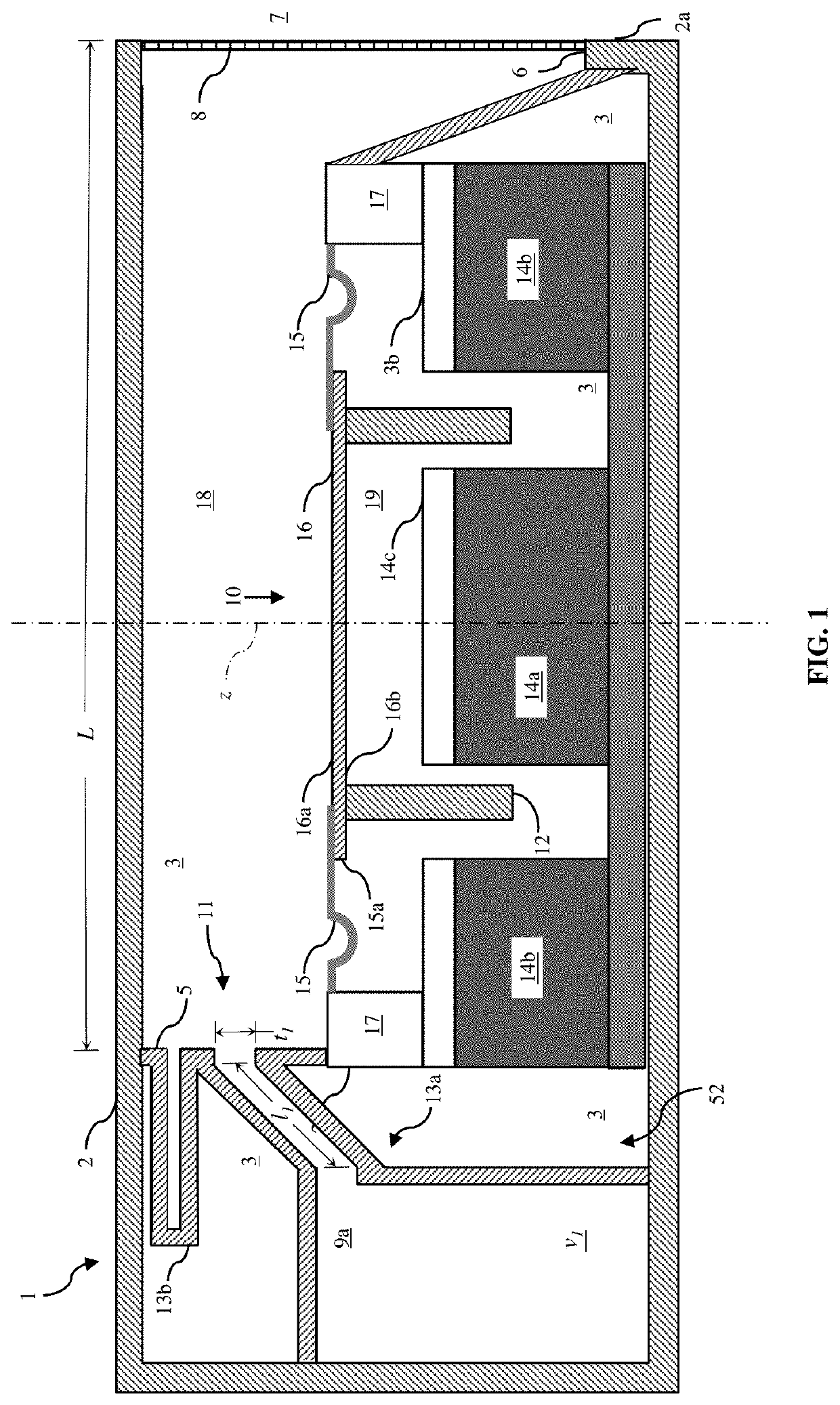
[0040]The following describes various principles related to acoustic chambers damped with one or more side-branch resonators, and related systems and methods. For example, some disclosed principles pertain to acoustic systems, methods, and components to damp resonance at certain frequencies, extending a frequency response of an acoustic enclosure. That said, descriptions herein of specific appliance, apparatus or system configurations, and specific combinations of method acts, are but particular examples of contemplated appliances, components, systems, and methods chosen as being convenient illustrative examples of disclosed principles. One or more of the disclosed principles can be incorporated in various other appliances, components, systems, and methods to achieve any of a variety of corresponding, desired characteristics. Thus, a person of ordinary skill in the art, following a review of this disclosure, will appreciate that appliances, components, systems, and methods having at...


PUM


Abstract

An acoustic enclosure includes a housing at least partially defining an acoustic chamber for an acoustic radiator. The housing further defines an acoustic opening from the acoustic chamber to a surrounding environment. The acoustic enclosure also has a first acoustic resonator and a second acoustic resonator. The first acoustic resonator and the second acoustic resonator are acoustically coupled with the acoustic chamber in parallel relative to each other. Each of the first acoustic resonator and the second acoustic resonator modifies a frequency response of the acoustic chamber. Loudspeakers can include such an enclosure acoustically excited or driven by an electro-acoustic transducer. As well, an electronic device can include such a loudspeaker.

Description

FIELD[0001]This application and related subject matter (collectively referred to as the “disclosure”) generally concern acoustic chambers damped with one or more side-branch resonators, and related systems and methods. More particularly, but not exclusively, this disclosure pertains to loudspeaker enclosures defining an acoustic chamber acoustically coupled with two or more side-branch resonators, with each respective side-branch resonator being configured to damp a corresponding resonant frequency.BACKGROUND INFORMATION[0002]Typical electro-acoustic transducers have an acoustic radiator and typical loudspeakers pair such an acoustic radiator with an acoustic chamber to accentuate and / or to damp selected acoustic frequency bands. Conventional acoustic chambers and acoustic radiators often are large compared to many electronic devices.[0003]For example, many commercially available electronic devices have a characteristic length scale equivalent to or smaller than a characteristic len...

Claims


Application Information

Patent Timeline
Patent Type & Authority Applications(United States)
IPC IPC(8): H04R1/28H04R1/02H04R9/06
CPCH04R1/2811H04R1/025H04R9/06H04R1/1016H04R1/1075H04R1/1083H04R1/2876H04R9/025H04R1/2849H04R1/2826H04R1/2842
Inventor PAVLOV, PETER M.BRUSS, JOHN R.LE, DUY P.
Owner APPLE INC
Why Eureka
Try Eureka