
Grab Rail with Automatically Activated Light

a technology of automatic activation and hand rails, applied in the field of hand rails, can solve the problems of rails or rails losing prominence in comparison to the rest of the surroundings, the same degree of observation, and the effect of being quite blinding

Active Publication Date: 2020-04-02
EVEKARE PTY LTD
View PDF6 Cites 8 Cited by
  • Summary
  • Abstract
  • Description
  • Claims
  • Application Information

AI Technical Summary

Benefits of technology

The invention is a grab rail that has several advantages over older designs. It uses noise activation and a light detector to automatically turn on the lights in a bar when someone opens a door. This provides light to the surrounding area while also highlighting the location of the grab rail if needed.

Problems solved by technology

However, when using facilities such as bathrooms during the night, when the main lighting is usually switched off, there is not the same degree of observation.
Similarly, if the user has to locate a light switch and turn it on when tired and sleepy, the effect is often quite blinding, and again the rail or rails lose prominence in comparison to the rest of the surroundings.
Clearly the need for mains power makes these difficult to retrofit into an existing building.
However, both of these options still require the user to consciously first find the switch in the dark to illuminate the rail.
While these products overcome the problems with mains power and switches, most facilities do not get enough daylight to adequately charge the luminescent materials to provide sufficient lighting throughout the night.
Another problem common to most prior art illuminated grab rail solutions is that the assemblies have a lot of join areas between the main rail and transparent lenses for lights, or between the rail and luminous edging or wraps, and / or the rail and the often cumbersome, rail support fixtures.
These joins can accumulate dirt and germs and are difficult to clean, and as a result such designs would not pass the strict hygiene requirements for many applications.
Additionally, other lighted grab rail designs require a lot of dismantling and / or dismounting to facilitate repair or service.

Method used


Image

  • Grab Rail with Automatically Activated Light
  • Grab Rail with Automatically Activated Light
  • Grab Rail with Automatically Activated Light

Examples


Embodiment Construction

[0031]The present invention will now be described with reference to the following examples which should be considered in all respects as illustrative and non-restrictive.

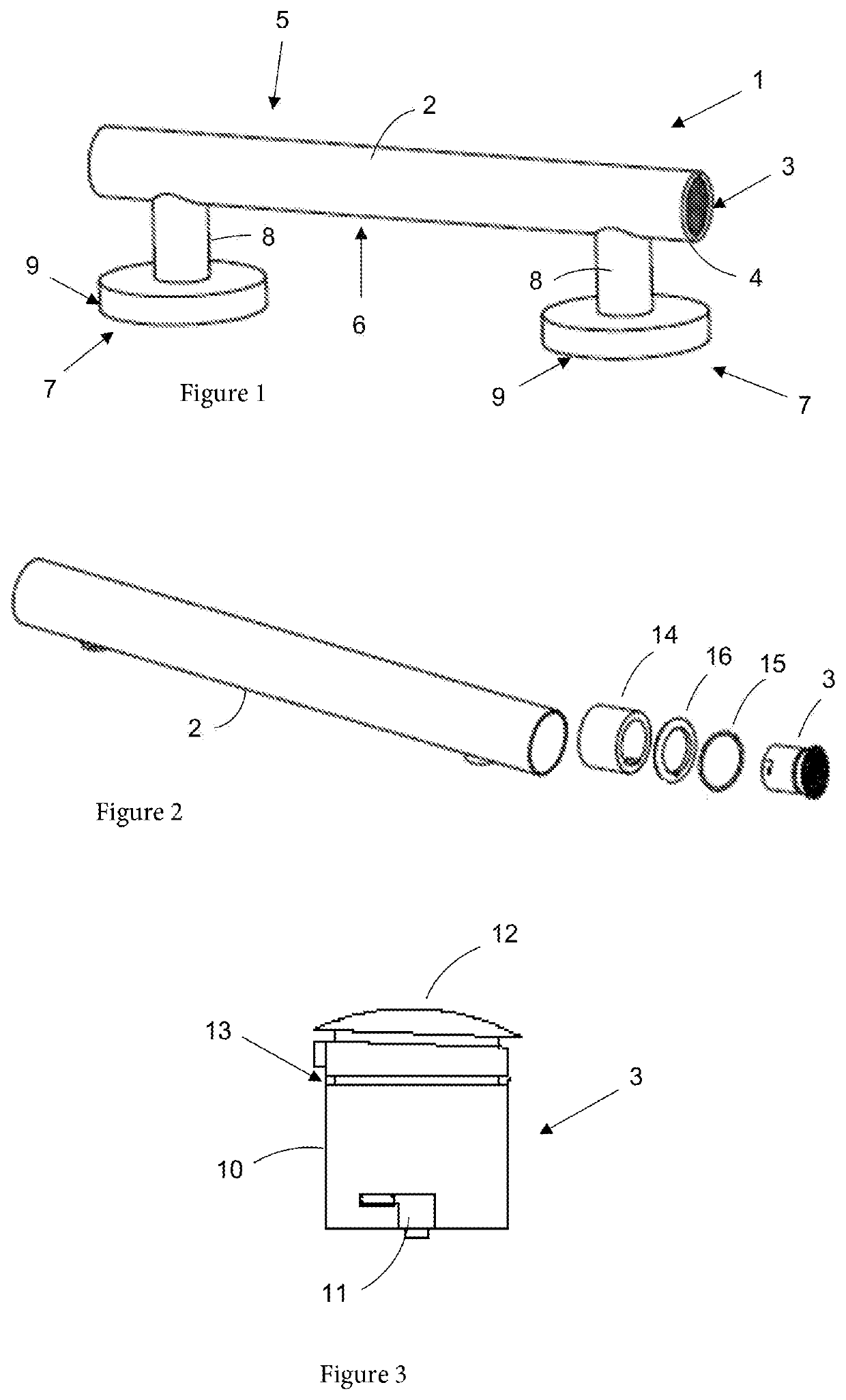
[0032]Referring firstly to FIG. 1 there is shown a first embodiment grab rail 1 according to the invention. The grab rail 1 includes a straight longitudinal tubular bar 2 that has an LED light unit 3 in each hollow end 4. In this preferred embodiment, the light units 3 include an integrated battery source and noise activated switching device.

[0033]The bar 2 has a front longitudinal face 5 that in use faces into a room, and a rear longitudinal face 6 which faces a surface to which the grab rail is to be mounted. Connected to the rear face 6 of the rail 2 are two post mounts 7. Each post mount includes a post 8 which connects with the bar 2 and a flange 9 for connection to a wall or other structure (not shown).

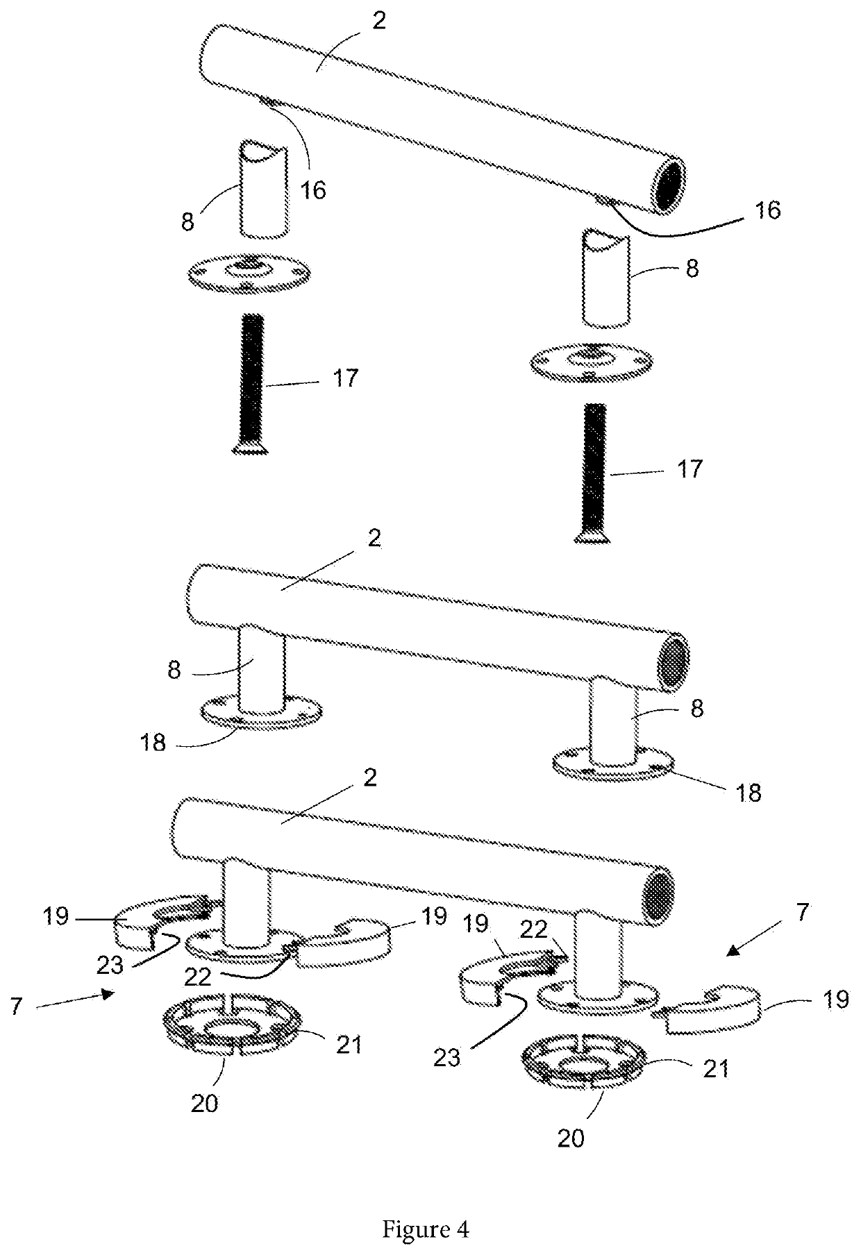
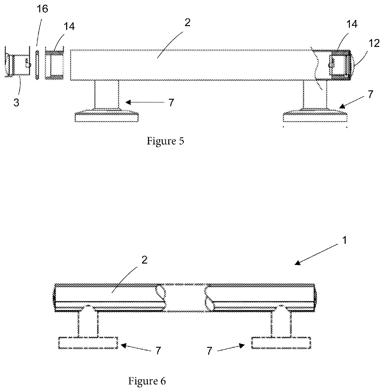
[0034]Turning next to FIGS. 2, 3 and 5 there is shown a currently preferred arrangement by which the preferre...


PUM


Abstract

A grab rail with automatically activated light including: a straight longitudinal bar having a front longitudinal face and a rear longitudinal face and hollow openings at each end; two light units, each sealingly but releasably secured in one of said hollow end openings; a battery source connected with the light units and located inside the bar; at least one noise activated switching device operatively associated with said LED light units and battery source; and at least one post mount with flange, wherein an end of the post distal the flange is secured to the rear longitudinal face of the bar.

Description

CROSS-REFERENCE TO RELATED APPLICATION[0001]This application claims priority to Australian Patent Application No. 2018903683 filed Sep. 28, 2018, the disclosure of which is hereby incorporated in its entirety by reference.FIELD OF THE INVENTION[0002]The present invention relates to hand rails used for physical support that are typically referred to as “or “grab rails” or “grab bars”.[0003]The invention has been developed primarily for retrofitting applications in bathrooms and other rooms in domestic residences and hotel and institutional accommodation facilities. However, it will be appreciated that the invention need not be limited to such applications.BACKGROUND OF THE INVENTION[0004]Any discussion of the prior art throughout the specification should in no way be considered as an admission that such prior art is widely known or forms part of common general knowledge in the field.[0005]Grab rails in the form of simple wall mounted rails have been used extensively in homes, care fa...

Claims


Application Information

Patent Timeline
IPC IPC(8): E04F11/18F21S4/20
CPCE04F11/1802F21V23/0442A47K3/003E04F2011/1872F21S4/20F21V33/0064A47K17/022F21W2111/08F21V23/0464F21V23/0471E04F11/1804F21S9/02F21V31/005F21Y2115/10
Inventor HOLLAND, GLENN
Owner EVEKARE PTY LTD
Learn More